
TV Muter Circuit
The described mute circuit effectively mitigates audio disturbances caused by channel switching on older tube-type televisions. By utilizing a simple IR receiver module, the circuit can detect remote control signals and activate a mute function, ensuring a seamless audio experience. The design incorporates key components such as comparators, transistors, and capacitors to achieve reliable performance. The adjustable reference voltage allows for fine-tuning based on specific system requirements, ensuring optimal operation across various setups. Furthermore, the option to use a relay with normally-closed contacts provides flexibility in design, allowing for energy-efficient operation. Proper shielding of the IR sensor enhances the circuit's resilience to ambient light interference, further improving overall functionality. This circuit presents a practical solution for integrating older television technology with modern audio systems, enhancing user experience by eliminating undesirable noise artifacts.Many households are still graced by tube-type television sets. If you want to connect one of these large tellies to your stereo system to improve the sound quality, this is usually not a problem because there are plenty of SCART to Cinch adapters available in accessory shops. However, with some sets your pleasure is spoiled by the fact that the audio outputs of the SCART connector are not muted during channel switching. This can sometimes lead to nasty signal spikes, which can cause the loudspeakers of your stereo system to emit irritating popping and cracking noises. In such cases it is a good idea to fit your system with a mute circuit. Fortunately, the right time to activate the mute circuit is defined by the fact that the happy zapper presses buttons on the remote control to switch channels, and the remote control emits IR signals.
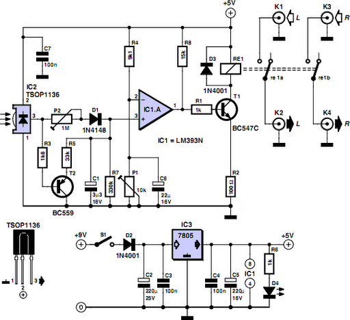
There are even inexpensive ready-made IR receiver modules available, such as the TSOP1136 used here, which produce trains of active-low pulses in response to such signals. About the circuit: when no IR signal is present, a capacitor is charged via P2 and a diode. IC1 is a comparator that compares this IR voltage (applied to its non-inverting input on pin 3) to a voltage applied to its other input on pin 2.
This reference voltage, which can be adjusted with P1, determines the switching threshold of the comparator. If IC2 receives an IR signal, T2 conducts, and as a result the voltage on C1 drops rapidly below the threshold level set by P1.
This causes T1 to change from its previous on` state to the off` state. As a result, the relay drops out and the audio link to the stereo system is interrupted for the duration of the noise interval. It`s all quite simple, as you can see. If you do not have a stabilized 5-V supply voltage available, you can use the circuit at the of the schematic diagram (with a 5-V voltage regulator) together with a simple (unstabilised) AC mains adapter that supplies a voltage in the range of 9 V to 12 V to the 7805 (IC3).
You can also use a relay with normally-closed contacts instead of normally-open contacts. In this case, simply swap the signals on pins 2 and 3 of IC1 so the relay pulls in when an IR signal is received instead of dropping out. This saves a bit of power because the relay is only energized during zapping. If you can`t find any worthwhile use for the second comparator of IC1, it`s a good idea to connect pin 6 to +5 V and pin 5 to ground.
To improve noise immunity, you should shield the IR sensor so it is not exposed directly to light from a fluorescent fixture. 🔗 External reference
Related Circuits

A CMOS-based circuit designed for adjusting the time of spot welding. This circuit utilizes a CMOS device that allows for cycle selection ranging from 1 to 99 cycles. In practical applications, most users find that adjustments within 10 cycles...
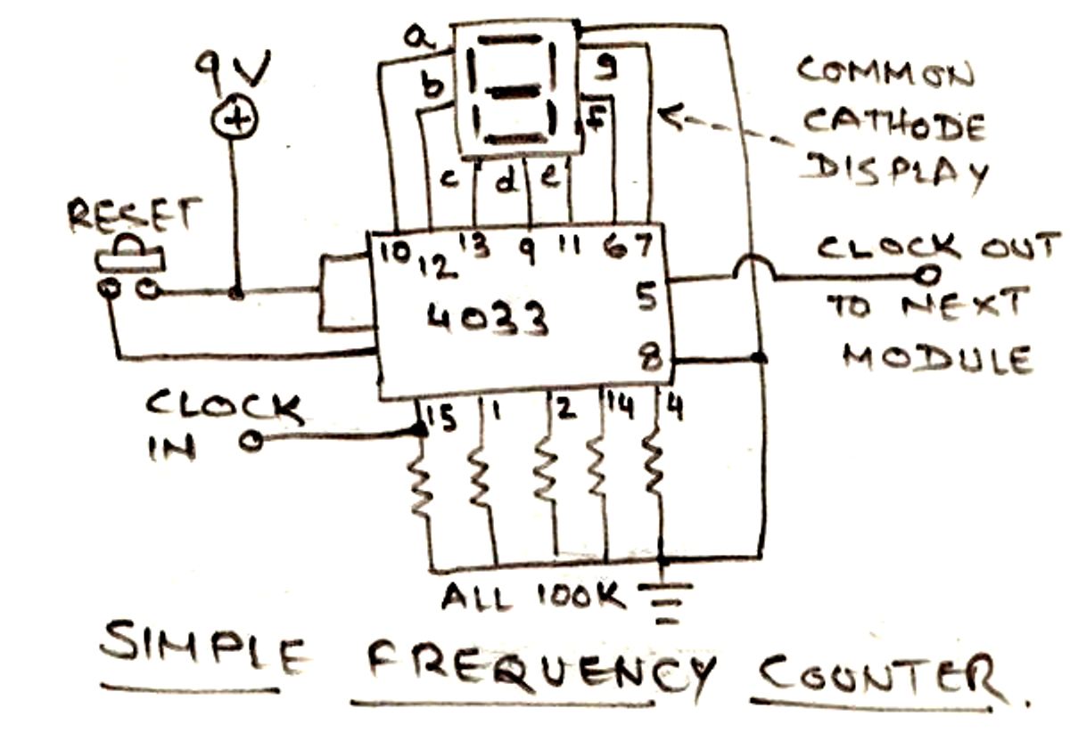
The circuit illustrated below is designed for measuring frequency in Hertz (Hz). It is straightforward to construct, utilizing a single IC 4033 and a common cathode display as the main components. For measuring higher frequencies, typically in the range...
Fuzz is one of the classic guitar effects, and this simple circuit generates it quite well. The circuit is so compact that it can be built into guitars or amps that do not have built-in fuzz to add that...
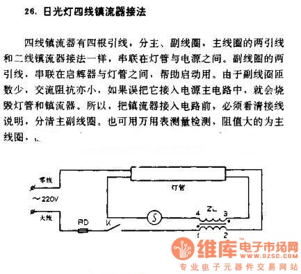
The four-wire ballast connection of a fluorescent lamp consists of four lead wires, which include main and auxiliary coils. The connection of the two lead wires in the main coil is similar to that of a second-line ballast; both...
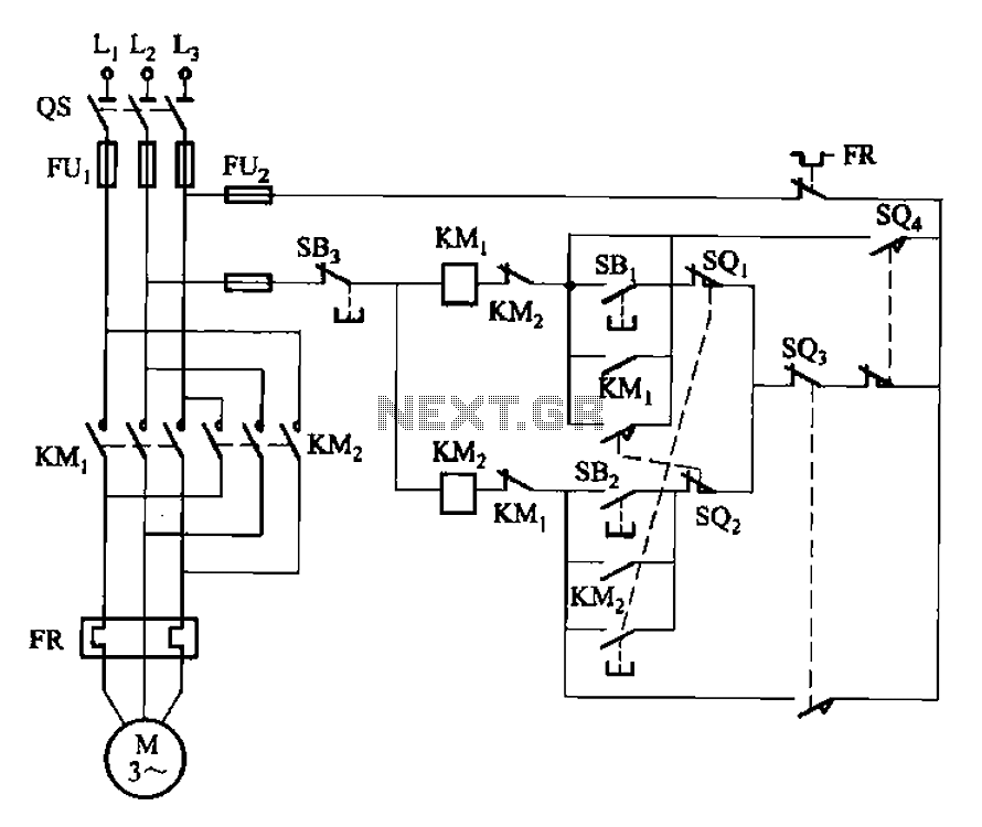
The circuit illustrated in Figure 3-132 represents an automatic round-trip plug braking circuit. To prevent or limit malfunctions of switch SQ1 and switch SQ2 that could lead to accidents, two additional protection limit switches, S03 and S04, have been...
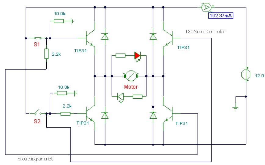
This is a DC motor controller circuit built using the TIP31 transistor based on the H-Bridge concept. The switches S1 and S2 are normally open, push-to-close buttons. The LED serves to indicate the direction of motor rotation and any...