
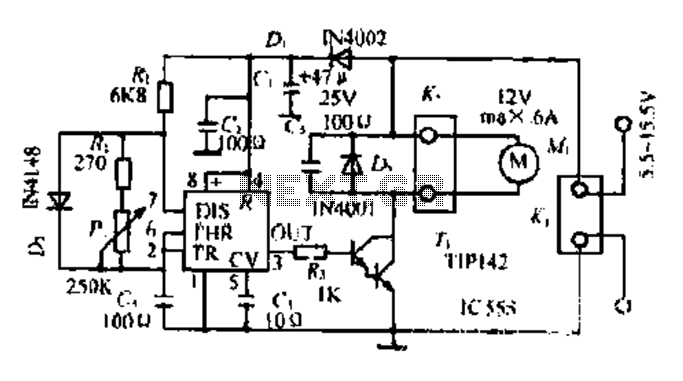
Servo pulse to PWM converter
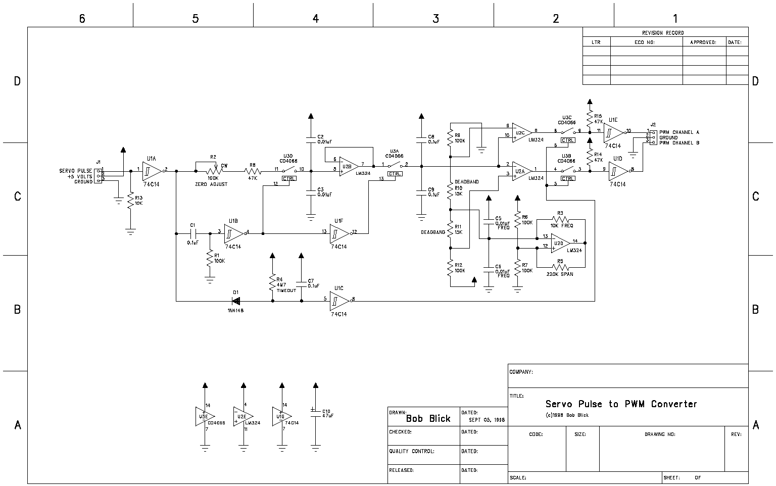
The described circuit functions as a pulse converter, transforming incoming pulses from devices such as a Basic Stamp or an R/C receiver into a dual PWM signal. This dual PWM output is essential for controlling the operation of an H-bridge, which is commonly used to drive DC motors in robotics and automation applications.
The design utilizes discrete components rather than a microcontroller, making it accessible for hobbyists and experimenters who may have these components readily available. The circuit typically includes resistors, capacitors, and possibly transistors or operational amplifiers to shape and modify the input signal into the desired PWM output.
In operation, the circuit receives the pulse signal from the Basic Stamp or R/C receiver. It processes these pulses by adjusting their width and frequency to create two separate PWM signals, which are then fed into the H-bridge. The H-bridge interprets these signals to control the direction and speed of the motor.
The choice of a traditional component-based approach over a microcontroller may also provide advantages in terms of simplicity and reliability, particularly in environments where programming may be less desirable or feasible. The total cost of the components is relatively low, comparable to that of a simple beverage, making it an economical solution for those looking to experiment with motor control without significant investment.
Overall, this circuit serves as a practical example of how traditional electronic components can be effectively utilized to achieve modern control applications.The circuit presented on this page attemps to be an interface to convert pulses such as provided by a Basic Stamp or R/C receiver to a dual PWM(Pulse Width Modulation) signal required by an H-bridge. The simplest circuit would use a small microcontroller like a PIC. This circuit takes a more traditional approach. Many experimenters will have all the parts already. Total parts cost should be equal to a simple espresso drink, although I have stopped drinking coffee I still remember how much it costs :-)
🔗 External reference
Related Circuits
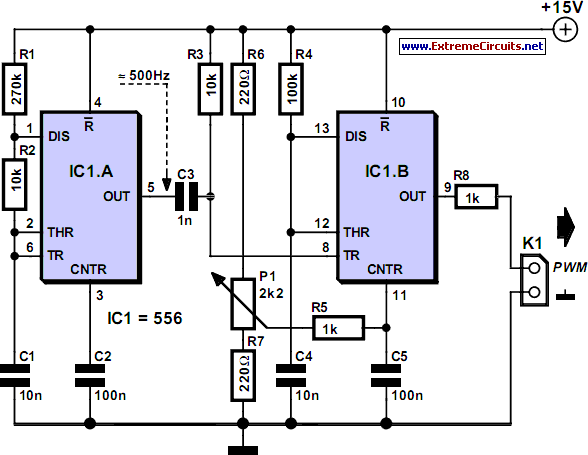
This circuit serves as an introduction to pulse-width modulation experimentation, utilizing a dual 555 timer for simplicity. A small PCB has been designed to facilitate construction. Although not an original design, it complements the "Dimmer with MOSFET" article on...
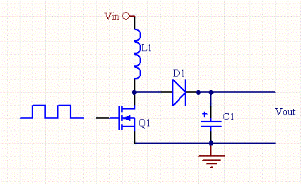
VD represents the voltage drop across the diode, while VTrans indicates the voltage drop across the transistor. The boundary between continuous and discontinuous operation occurs when the output current (io) is zero. A primary consideration in converter design is...
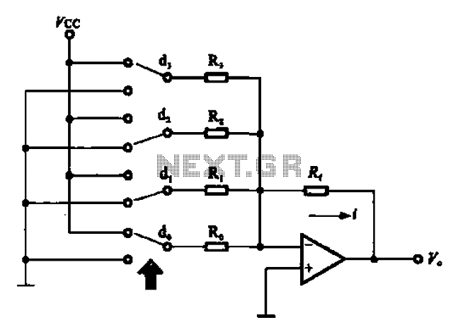
An A/D converter circuit can be represented by a simplified schematic, which illustrates a parallel type A/D converter. The term "median" refers to the number of bits in the digital signal output. The figure displays four A/D converters utilizing...
Most governors utilize pulse width modulation (PWM) and pulse position modulation (PPM) in their circuits. The 555 timer is commonly used in these applications. The pulse width is typically fixed at 0.5 milliseconds, which is essential for the functioning...
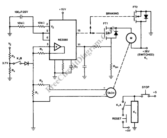
Closed loop motor control is utilized for maintaining constant speed in motor operations. This means that the motor's speed is regulated to remain steady. Closed loop motor control systems, commonly referred to as servo control systems, are essential in applications...
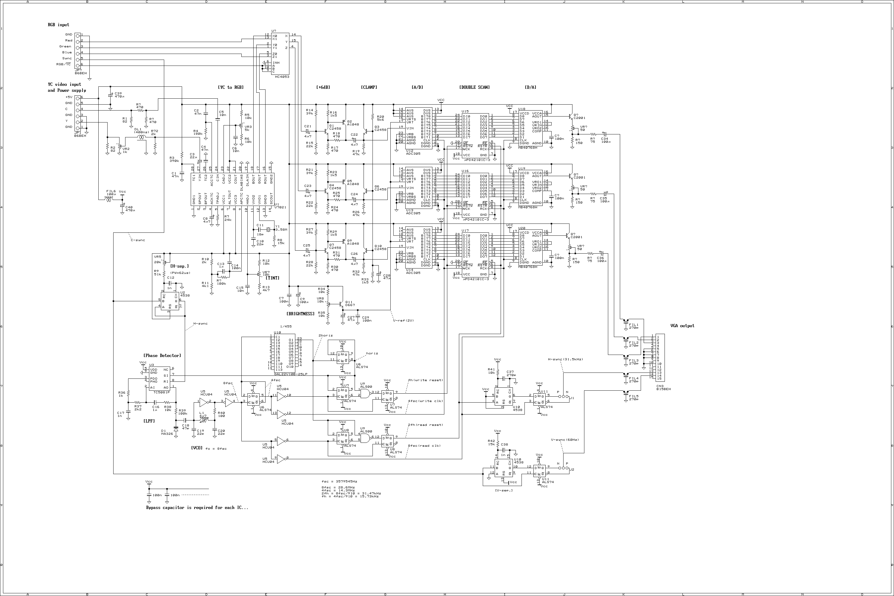
This is a video scan converter to display NTSC video signal into VGA monitor. Normally, the VGA monitor occupies most desk top space, so that everybody will be thinking that if the VGA monitor can be used for video...
Warning: include(partials/cookie-banner.php): Failed to open stream: Permission denied in /var/www/html/nextgr/view-circuit.php on line 713
Warning: include(): Failed opening 'partials/cookie-banner.php' for inclusion (include_path='.:/usr/share/php') in /var/www/html/nextgr/view-circuit.php on line 713