
GBPPR 1 GHz RF Spectrum Analyzer

The RF spectrum analyzer project entails a systematic approach to the design and construction of a high-performance device for analyzing radio frequency signals. The project architecture emphasizes modularity, allowing for individual components to be shielded and isolated, which is critical for minimizing interference and enhancing signal integrity. The use of a Mini-Circuits SRA-11 mixer as the core component for frequency conversion is pivotal, as it facilitates the handling of a wide frequency range. The integration of a bandpass cavity filter constructed from copper plumbing parts serves to refine the signal further, ensuring that only the desired frequency components are processed.
The design also incorporates state-of-the-art logarithmic detection and amplification techniques, utilizing components such as the Analog Devices AD603 and AD8307 to achieve accurate signal representation. The implementation of a sweep generator allows for dynamic analysis, making it possible to visualize the frequency spectrum over time on an oscilloscope. This capability is essential for experimenters looking to analyze transient signals or for observing the behavior of RF components under varying conditions.
Moreover, the project highlights the importance of using high-quality coaxial cables and connectors to maintain signal fidelity throughout the system. The use of RG-142 or conformable coax like UT-141 ensures that signal losses due to cable attenuation and external noise are minimized. The emphasis on proper voltage regulation and filtering for each module is also crucial for maintaining stable operation and preventing noise from affecting the performance of sensitive RF components.
In summary, this RF spectrum analyzer project not only builds upon existing designs but also introduces enhancements that improve performance and usability. The detailed attention to shielding, modular design, and high-quality components contributes to a robust tool for RF experimentation and analysis.A RF spectrum analyzer is one of the most useful tools an experimenter can have. The spectrum analyzer project shown here will be a slight improvement on the " Spectrum Analyzer for the Radio Amateur " ( Part 2 ) project from Wes Hayward (W7ZOI) and Terry White (K7TAU) which was covered in the August and September issues of QST magazine. There will also be a few ideas taken from the Scotty`s Spectrum Analyzer project by Scotty Sprowls, most notably, his really nice first IF (1013. 3 MHz) bandpass cavity filter. You must read and study carefully the " Spectrum Analyzer for the Radio Amateur " article before embarking on this project, as it covers some of the more in-depth concepts and construction notes which will not be covered here.
Wes Hayward also has several " Spectrum Analyzer Update " PDF files on his website which should also be studied as they include a number of tweaks and improvments to his design. These update files also include the necessary final IF/logarithmic amplifier calibration information.
Most of the components used in this RF spectrum analyzer project were obtained from ham radio swapfests or salvaged from old two-way radios, cellular phones, or cable TV distribution gear. Some components may be hard to track down, but equivalent parts can be substituted with minor tweaking of the circuits.
No PCB patterns will be provided as all the PC board layouts were done by hand using Sharpie markers and a straight edge. You`ll want to keep the PC board traces as short as possible and utilize a large ground plane and isolate the RF inputs and outputs.
The PC boards were all made from double-sided (1 oz. ) 1/32-inch FR4 material. The key to building a high-performance RF spectrum analyzer is isolation and shielding. Construct the spectrum analyzer as a series of well-shielded modules which each perform only one function. This will also make debugging (and future modifications) much easier. All the individual modules and their interconnections should be shielded and filtered. Coax jumpers should be high-quality RG-142, or (ideally) 100% shielded comformable coax like UT-141. Failing to properly do this will result in numerous spurious images in the final displayed spectrum. Voltage regulators will also not be documented in the schematics, but try to use the newer, lower-noise equivalents of the common three-terminal voltage regulators.
The two VCOs should be operated off of a separate voltage regulator from the other circuits. Each module should have its own voltage regulator, with feed-through capacitors and ferrite beads on the incoming lines, for the best interference/noise rejection performance. This spectrum analyzer will consist of an incoming RF signal, up to 1000 MHz and -30 dBm max. , feeding a Mini-Circuits SRA-11 mixer which has a sweeping Local Oscillator (LO) signal from 1013 to 2013 MHz.
This mixer will create a 1013. 3 MHz first IF output which will then be sharply bandpass filtered using a 4-pole cavity filter made from copper pipe plumbing parts. The 1013. 3 MHz first IF will then feed another Mini-Circuits SRA-11 mixer which has a fixed LO signal of 1024 MHz.
This mixer will produce the final IF frequency of 10. 7 MHz. The 10. 7 MHz IF signal will then pass through a narrowband resolution filter and then onto additional IF amplification and logarithmic detection using an Analog Devices AD603 and AD8307. The final video output signal will be a logarithmic representation of the incoming RF signal and will drive the "Y" input (0.
5 V/div) on an oscilloscope operating in "X/Y" mode. A sweep generator will control both the sweeping first local oscillator and the "X" input (0. 5 V/div) on the oscilloscope. Component changes in several pictures are due to constant tweaking. Refer to the schematics for the final design. Updates to this project will be available at. ZMSW-1211 PIN diode switches are often available at swapfests for very low cost an 🔗 External reference
Related Circuits
This analyst is a sensitive instrument in the frequency changes and width of an acoustic signal. Thus, the brightness of the LED that turns on each moment is proportional to the signal width, while the color is proportional to...
The traditional transistor power supply features a large filter capacitor on the rectifier output, followed by an electronic regulator that eliminates all voltage fluctuations, including ripple. During the era of vacuum tubes, only high-end test equipment from manufacturers like...
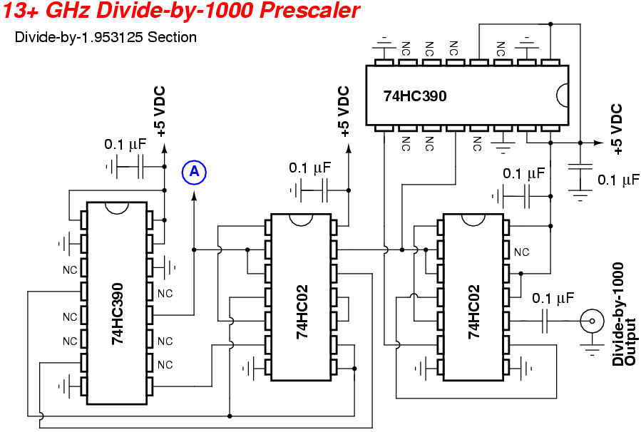
A straightforward "divide-by-1000" circuit was originally designed by Zeljko Bozic, S52ZB, in a 2006 issue of VHF Communications Magazine. This project aims to extend the range of older and more affordable frequency counters. Frequency counters capable of measuring up...
The circuit consists of a few components, specifically four, to create a miniature wireless FM microphone. It operates with a stable frequency, achieving a range of over 10 meters with a 1.5V supply and a current consumption of less...
This instrument is a sensitive analyzer that detects changes in frequency and the width of an acoustic signal. The brightness of the LED that activates at any given moment is proportional to the width of the signal, while the...
This document describes a simple 2.4 GHz SWR meter that utilizes surplus microwave hardware. The main component is a MECA -20/-20 dB Directional Coupler, which operates within a frequency range of approximately 700 MHz to 2.5 GHz. This directional...