
Geiger Counter
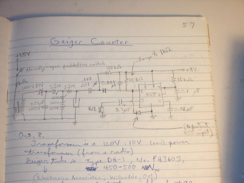
The simple Geiger counter circuit typically consists of a Geiger-Müller (GM) tube, which is the primary sensing element that detects ionizing radiation. The GM tube is connected to a high-voltage power supply, usually ranging from 400 to 900 volts, to create an electric field within the tube. When radiation passes through the tube, it ionizes the gas inside, leading to a cascade of electrons that generates a measurable current pulse.
The circuit often includes a resistor in series with the GM tube to limit current and protect the tube from excessive voltage. A capacitor may also be employed to smooth out voltage fluctuations, ensuring stable operation. Additionally, a transistor or operational amplifier may be used to amplify the pulse signal generated by the GM tube for further processing.
To provide a user-friendly interface, the circuit may incorporate a microcontroller or a simple analog meter to display the radiation levels detected. An audible alarm or LED indicator can be added to alert users when radiation exceeds a predefined threshold.
Power supply considerations are crucial; the circuit can be powered by batteries or an external power source, with appropriate voltage regulation to maintain the necessary operating conditions for the GM tube.
In summary, this simple Geiger counter circuit is designed for effective radiation detection, utilizing a Geiger-Müller tube, high-voltage supply, and additional components for signal processing and user notifications.Publishing this one in a hurry, in case it is useful to our friends in Japan. This is a simple Geiger counter circuit. It does require some speciali.. 🔗 External reference
Related Circuits
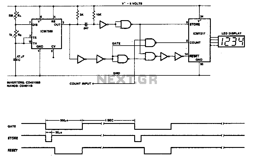
This circuit utilizes the low-power ICM7555 (CMOS 555) to generate the gating, STORE, and RESET signals. The timer is configured as an astable multivibrator to provide the gating signal. Calibration of the system is achieved using a 5 MΩ...
For convenient reading, the display of this tachometer circuit shows the reading in hertz directly. The conversion time will be equal to the gating time. The tachometer circuit is designed to provide a direct digital readout of rotational speed in...
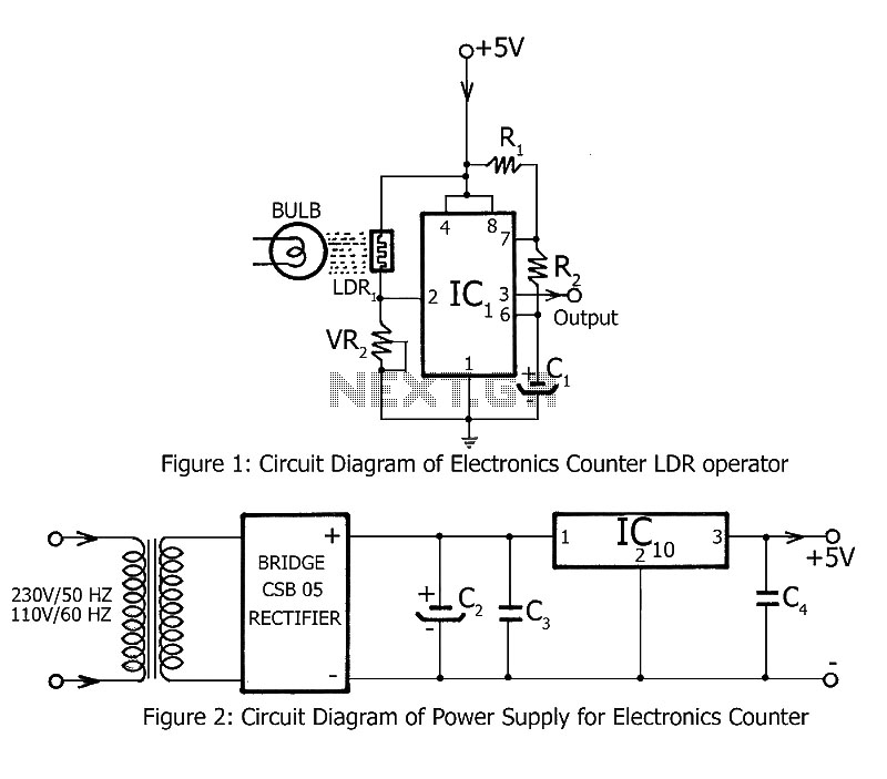
Simple counting can be performed by anyone, but counting over large intervals can be tedious and prone to errors. A previously published project, the Digital Counter, serves as a foundation for this electronics counter, which is the second project...
The heart of the lock is the 40022 octal counter. When first powered C2 is charged via R5 so the reset input of the counter is kept high. That causes output Q to go high while all the other...

This Project Automatic Room Light Controller with Visitor Counter using Microcontroller is a reliable circuit that takes over the task of controlling the room lights as well as counting the number of persons/visitors in the room very accurately. When...
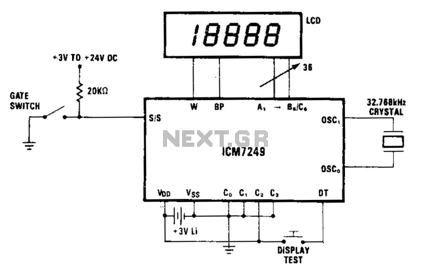
The display indicates each increment. In mode 2, external debouncing of the gate switch is unnecessary, provided that the switch bounce duration is less than 35 ms. The 3 V lithium battery can be replaced without interrupting operation if...