
getting started with sn 6675

The following outlines part of the sample source code. The microcontroller used in this tutorial is the PIC16F887, with MPlab X version 1.20 and XC8 compiler version 1.0 available for download. For more information, refer to the MPlab X tutorial. The main function is responsible for reading the temperature from the SN-6675. A sub-function detects the 12 bits of data received by the MAX6675 by shifting the bits 16 times before sending it back to the PIC16F887. The code demonstrates a virtual SPI function that generates a clock pulse 16 times to receive the data in 16 bits. This sub-function, which utilizes the virtual SPI function, can be found in the MAX6675 library.
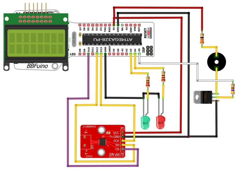
The SN-6675 breakout board is an efficient solution for temperature measurement, utilizing the MAX6675 thermocouple-to-digital converter. This device is designed to work specifically with K-type thermocouples, providing a temperature measurement range from 0°C to +1024°C. The output resolution of 0.25 degrees ensures high precision in temperature readings, making it suitable for various applications.
The SPI (Serial Peripheral Interface) communication protocol is employed to facilitate data transfer between the SN-6675 and the microcontroller, in this case, the PIC16F887. The SPI interface requires three digital I/O pins: one for the clock signal, one for the data output from the SN-6675, and one for the chip select signal to activate the MAX6675. The communication process is initiated by the microcontroller generating a clock signal, which synchronizes the data transfer.
The MAX6675 chip processes the temperature data by converting the analog signals from the thermocouple into a digital format. It outputs the temperature data in a 12-bit format, which is then read by the microcontroller. The sub-function responsible for data reception utilizes bit-shifting techniques to correctly align the incoming data for processing. The virtual SPI function is critical in this process, generating the necessary clock pulses to ensure the data is received accurately.
This setup allows for seamless integration of temperature measurement capabilities into various electronic projects, enabling users to monitor temperature with minimal complexity. The SN-6675 breakout board, along with the provided sample code, serves as an excellent starting point for developers looking to implement thermocouple-based temperature sensing in their designs.In order to measure the temperature without using the thermometer, thermocouples are the option to do so. However, the thermocouples need a reference temperature(normally take 0°C ) as to detect the difference of the temperature in between the materials of the thermocouples and is very inconvenience for the user to use it.
Hence, SN-6675 is introduced to do everything for you.This SN-6675 breakout board comes along with MAX6675 and a bypass capacitor. Specification: Works with K type thermocouple 0°C to +1024C output in 0.25 degree increments Internal temperature reading SPI data output requires any 3 digital I/O pins.
The following show some part of the sample source code.. The microcontroller used for this tutorial is PIC16F887. The MPlab X version 1.20 and XC8 compiler version 1.0 can be downloaded from here Please refer here for MPlab X tutorial main function: This function was functioning as to read the temperature from the SN-6675. Sub-function: Since the MAX6675 receive 12 bits of data at once, this function detects the data received by shifting the bits received as much as 16 times before sending it back to PIC16F887.
The following code shows the virtual SPI function generating the clock pulse 16 times in order to receive the data in 16 bits. Sub-function: Since the MAX6675 was received 12 bits of data at once, this function was detected the data received by shifting the bits received as much as 16 times before send it back to main function.
The code following was using the virtual SPI function by generate the clock pulse by 16 times in order to received the data by 16 bits. This sub-function can be found from the MAX6675 library. 🔗 External reference
Related Circuits
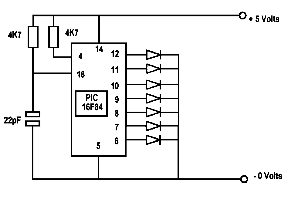
Several years ago, a colleague suggested the use of PICs for hobby projects, specifically amateur television. Extensive time was spent developing and experimenting with video mixers, faders, and effects units using analog and digital circuits (TTL gates), which often...
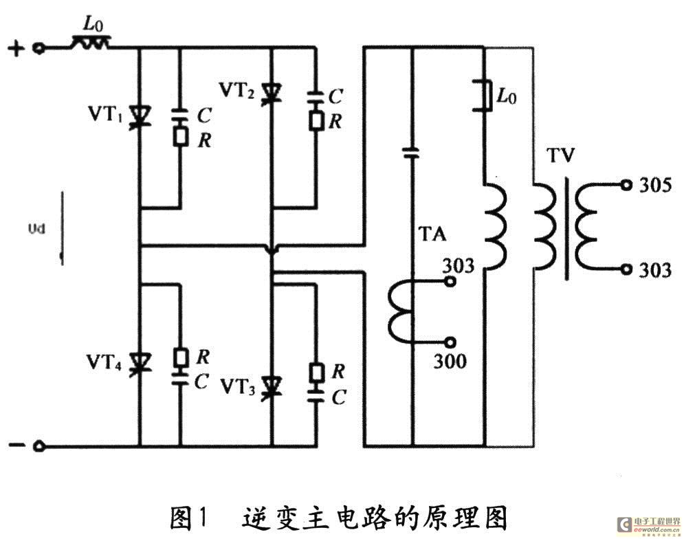
The starting ability of intermediate frequency power is a crucial performance index that significantly impacts the quality and usability of the apparatus. This has been a focal point and a challenge in the industry, leading to various methods aimed...
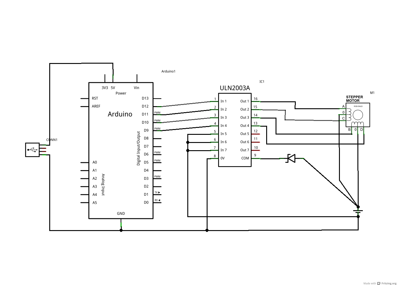
The ULN2003A and Zener diode are components from the driver board within the same device. The motor in question has five wires, while the schematic depicts a six-wire motor. It is assumed that the difference lies in the fact...
A drink mixer inspired by BAR2D2 utilizes a gravity-fed pump that operates on a 9V battery. The circuit incorporates a 555 timer to control the duration of the pump's operation. When connected directly to the battery, the pump functions...
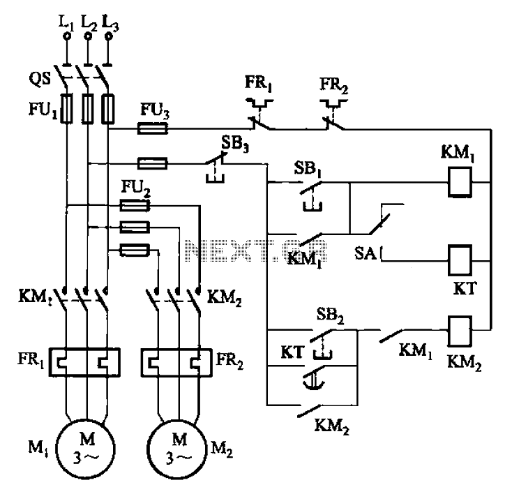
The circuit illustrated in Figure 3-85 features both manual and automatic control through the transfer switch SA. After initiating the motor Mi, an automatic start sequence is achieved via the time relay KT. The circuit employs a transfer switch (SA)...
The objective is to design a square-wave generator with an output range of 0 to +5V. Additionally, the design should allow for the modification of the signal to enable adjustment of the duty cycle of the pulse (PWM). The square-wave...