
improved 3 transistor audio amp

The circuit design incorporates a feedback mechanism that enhances the performance of the audio amplifier by utilizing positive feedback. The primary components consist of two NPN transistors, a capacitor, diodes, and resistors, which collectively facilitate the amplification process. The positive feedback loop is achieved through the strategic arrangement of the load resistor and the capacitor.
The 1kΩ load resistor connected to the speaker plays a critical role in managing the output signal. When the output signal swings negatively, the voltage across this resistor decreases, effectively turning off the top NPN transistor, which prevents distortion during the negative cycle of the audio waveform. Conversely, when the output swings positively, the charge stored in the 470µF capacitor provides additional base current to the top NPN transistor, enhancing its conduction and allowing for a stronger output signal.
The use of diodes in place of the resistor allows for better performance at lower supply voltages, which is particularly beneficial in battery-operated devices. The diodes maintain a stable bias voltage that adjusts as the battery discharges, minimizing crossover distortion which can adversely affect audio quality.
It is essential to ensure that the biasing of the output transistors is properly set to avoid overheating. The idle current should be carefully monitored, as excessive current can lead to thermal runaway conditions, potentially damaging the transistors.
Overall, this circuit represents a practical approach to audio amplification, balancing simplicity, efficiency, and performance, making it suitable for small-scale audio applications where space and power consumption are critical considerations.This circuit is similar to the one above but uses positive feedback to get a little more amplitude to the speaker. I copied it from a small 5 transistor radio that uses a 25 ohm speaker. In the circuit above, the load resistor for the driver transistor is tied directly to the + supply. This has a disadvantage in that as the output moves positive, the drop across the 470 ohm resistor decreases which reduces the base current to the top NPN transistor. Thus the output cannot move all the way to the + supply because there wouldn`t be any voltage across the 470 resistor and no base current to the NPN transistor.
This circuit corrects the problem somewhat and allows a larger voltage swing and probably more output power, but I don`t know how much without doing a lot of testing. The output still won`t move more than a couple volts using small transistors since the peak current won`t be more than 100mA or so into a 25 ohm load.
But it`s an improvement over the other circuit above. In this circuit, the 1K load resistor is tied to the speaker so that as the output moves negative, the voltage on the 1K resistor is reduced, which aids in turning off the top NPN transistor. When the output moves positive, the charge on the 470uF capacitor aids in turning on the top NPN transistor.
The original circuit in the radio used a 300 ohm resistor where the 2 diodes are shown but I changed the resistor to 2 diodes so the amp would operate on lower voltages with less distortion. The transistors shown 2n3053 and 2n2905 are just parts I used for the other circuit above and could be smaller types.
Most any small transistors can be used, but they should be capable of 100mA or more current. A 2N3904 or 2N3906 are probably a little small, but would work at low volume. The 2 diodes generate a fairly constant bias voltage as the battery drains and reduces crossover distortion. But you should take care to insure the idle current is around 10 to 20 milliamps with no signal and the output transistors do not get hot under load.
The circuit should work with a regular 8 ohm speaker, but the output power may be somewhat less. To optimize the operation, select a resistor where the 100K is shown to set the output voltage at 1/2 the supply voltage (4. 5 volts). This resistor might be anything from 50K to 700K depending on the gain of the transistor used where the 3904 is shown.
🔗 External reference
Related Circuits
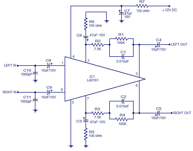
The LA3161 is an integrated two-channel preamplifier designed for car stereo applications. It operates on a 12V DC power supply. The LA3161 preamplifier is specifically engineered to enhance audio signals in automotive environments, ensuring optimal sound quality for car stereo...
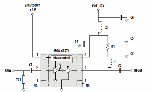
This application note discusses the use of Avago Technologies' MGA-675T6 for 5-6 GHz applications. The MGA-675T6 is internally integrated with shutdown and biasing circuitry, which simplifies the external circuitry. The shutdown feature allows the low noise amplifier (LNA) to...
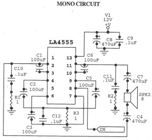
The following circuit illustrates an audio amplifier mono circuit diagram. This circuit is based on the LA4555 integrated circuit (IC). Features include a mono configuration and a power output of 2.3 watts. The audio amplifier circuit utilizing the LA4555 IC...
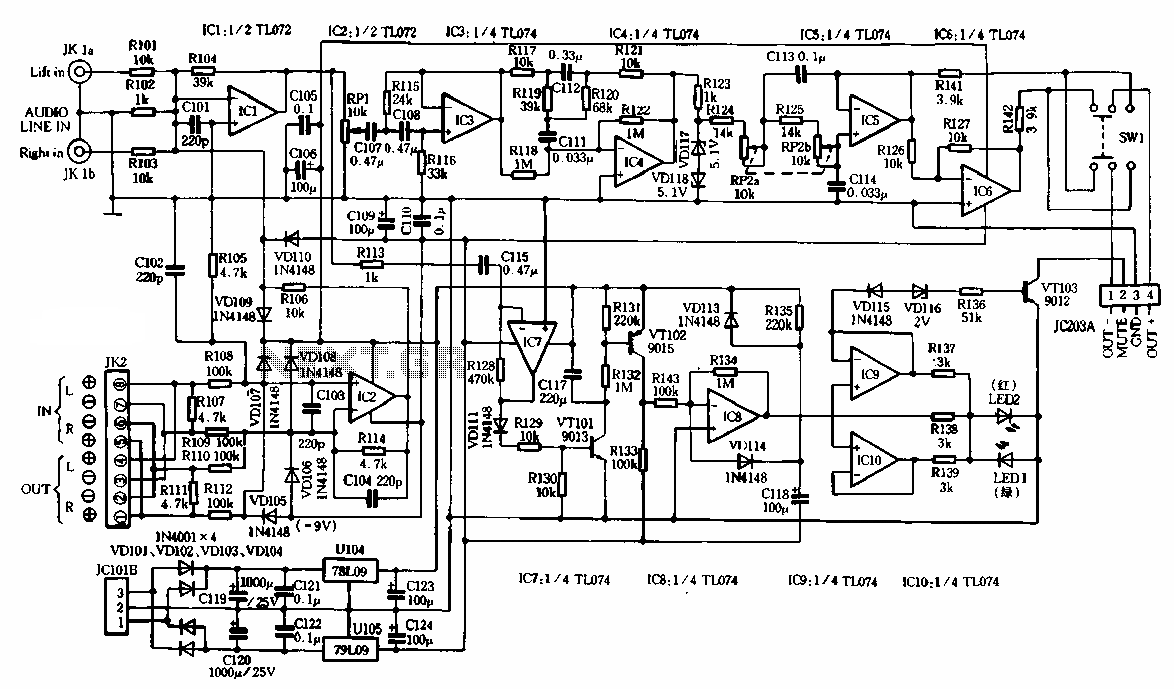
The schematic illustrates the subwoofer amplifier stage, specifically the pre-amplifier circuit and the signal processing circuit. Notably, it features two LM3886 power ICs from the American company NS, which facilitate BTL (Bridge-Tied Load) speaker operation at an 8-ohm impedance...
The amplifier circuit is highly suitable for use in FM radio receivers. It requires a supply voltage of 8 to 25 Volt DC and can deliver a maximum output power of 0.15W. Refer to the schematic below. The described amplifier...
The Maya utilized several calendars concurrently, one of which is known as the "long count." This calendar is a continuous record of days starting from a zero date that corresponds to August 13, 3114 BC. According to the Maya...