
Instrument panel lamp dimmer control Circuit
The circuit design employs the MC3392 as a low-side switch, which provides a safe method for controlling the power to the lamps. The low-side switching configuration allows for simpler control of the load and helps in managing the heat dissipation effectively. The MC1455 timer serves as the core of the PWM signal generation. By configuring the MC1455 in astable mode, it produces a continuous square wave output, the frequency of which can be adjusted by varying the resistance of the connected potentiometer.
The output frequency of approximately 80 Hz is optimal for automotive applications, as it minimizes the perception of flickering by the human eye, ensuring a smooth and consistent illumination of the panel lamps. The duty cycle adjustment allows for fine-tuning of the lamp brightness, catering to user preferences or specific requirements of the vehicle's instrumentation.
The circuit's design also includes a current limiting feature, ensuring that the total load does not exceed 1 amp, which is crucial for maintaining the integrity of the components and preventing potential damage. The inclusion of an LED indicator enhances the functionality of the circuit by providing visual feedback in the event of a fault condition, allowing for quick diagnosis and troubleshooting. This comprehensive approach to automotive lamp dimming not only enhances user experience but also contributes to the overall safety and reliability of the vehicle's electrical system.This circuit uses an MC3392 low side protected switch and an MC1455 timing circuit to form an automotive instrumentation panel lamp dimmer control. The brightness of incandescent lamps can be varied by Pulse Width Modulating the input of the MC3392.
The modulating signal can be obtained directly from the MC1455 timer (or a microprocessor). The MC1 455 is configured as a free-running clock having a frequency and duty cycle control. The typical timer frequency is approximately 80 Hz when the frequency potentiometer is adjusted to 1. 0k. This frequency was chosen so as to avoid any perceptible lamp flicker. The duty cycle potentiometer controls the duty cycle over a range of about 3% to 97%. When at 3% the lamps are essentialy off, at 97% the lamps are essentially full on. Any number of lamps can be control, so long as the total load current is less than 1 amp. The LED is used to signal the existence of a system fault (overvoltage, current limiting, or thermal shutdown).
🔗 External reference
Related Circuits
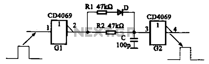
The inverter circuit using CD4069 is configured with a delay and width adjustment. When the output of the inverter (G1) is high, the capacitor (C) charges through resistor (R1) and diode (D). The voltage across capacitor C quickly reaches...
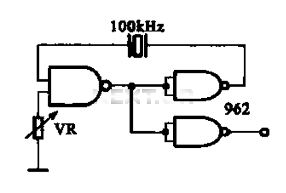
A DTL integrated circuit comprises a crystal oscillator, which is represented by the integrated circuits. The oscillation frequency ranges from 100 kHz to 1 MHz. Additionally, it includes a gate circuit that supplies a signal for the DTL oscillator...
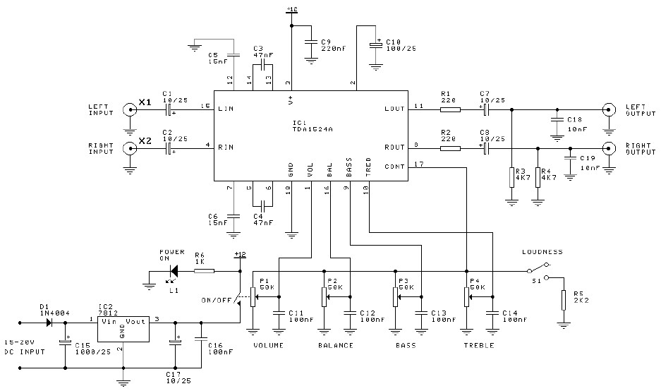
Preamplifier and tone control circuit based on the TDA1524A. The tone control circuit module is included in this preamplifier circuit, allowing for direct connection of the output channels to a stereo power audio amplifier circuit. This RIAA stereo preamplifier...
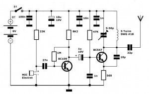
Simple FM Transmitter Circuit This simple FM transmitter circuit was built using a transistor with a transmission distance of about 300m around your home. The simple FM transmitter circuit utilizes a transistor to modulate audio signals onto a radio frequency...
The circuit below is designed to be used with the bi-directional lamp sequencer shown above on this same page. Two additional transistors are used to increase the current from the 74HCT138 decoder to control 12 volt 25 watt lamps....

A high-power and efficient 100W power amplifier electronic project can be designed using the STK404 audio power amplifier hybrid ICs. These ICs consist of optimally designed discrete component power amplifier circuits that have been miniaturized using SANYO's unique insulated...