
Thermistor lights lighting delay circuit
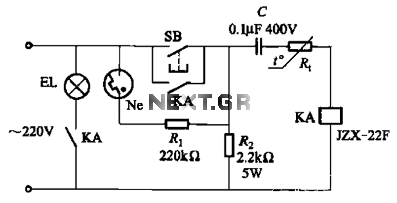
The circuit operates based on the thermal characteristics of the PTC thermistor, which exhibits a significant increase in resistance as the temperature approaches its Curie point. Initially, when the circuit is powered on, the thermistor remains cold, allowing current to flow through it and the lamp, resulting in illumination. As the lamp heats up, the temperature of the thermistor rises, leading to an increase in its resistance. This change in resistance effectively reduces the current flowing through the lamp, thereby controlling its brightness and extending the delay time before it turns off.
Adjustable resistor Rz plays a critical role in fine-tuning the delay time. By varying its resistance, the user can change the time it takes for the thermistor to reach its Curie point and thus modify the duration of the lamp's illumination. The value of the capacitor C is also essential, as it influences the charging time and, consequently, the delay time. A larger capacitance will result in a longer delay, while a smaller capacitance will shorten the delay.
The close contact requirement between resistors Rt and R2 ensures that they effectively sense the thermal changes in the circuit. This configuration is vital for accurate temperature measurement and response, allowing the circuit to function reliably under varying operational conditions. The overall design is simple yet effective, providing a practical solution for applications requiring controlled delay timing in lighting systems. Circuit shown in Figure 2-49. The circuit is very simple, cold PTC thermistor element, jump characteristic thermal resistance of the lamp to control delay time. Usually the del ay time is 10 ~ 30s, such as to change the delay time, adjustable Rz, the value of C. R. Adopt a positive temperature coefficient of thermal PTC thermistor, the choice of the Curie point about 80, nominal resistance value at 20 rise when 1500,80 to several thousand Euro to several tens of kilohms. Rt and R2 is required intimate contact.
Related Circuits
Two circuits for laser transmitters are described. The first circuit utilizes a simple laser pointer module, with 3 or 5mW devices functioning effectively. Higher power units are often imported from the USA or Hong Kong compared to UK approved...
The subwoofer is a speaker designed to reproduce low frequencies, specifically in the range of 20 Hz to 150 Hz. The electronic circuit diagram below illustrates the details of a subwoofer amplifier using the TDA1516, a 22-watt amplifier suitable...
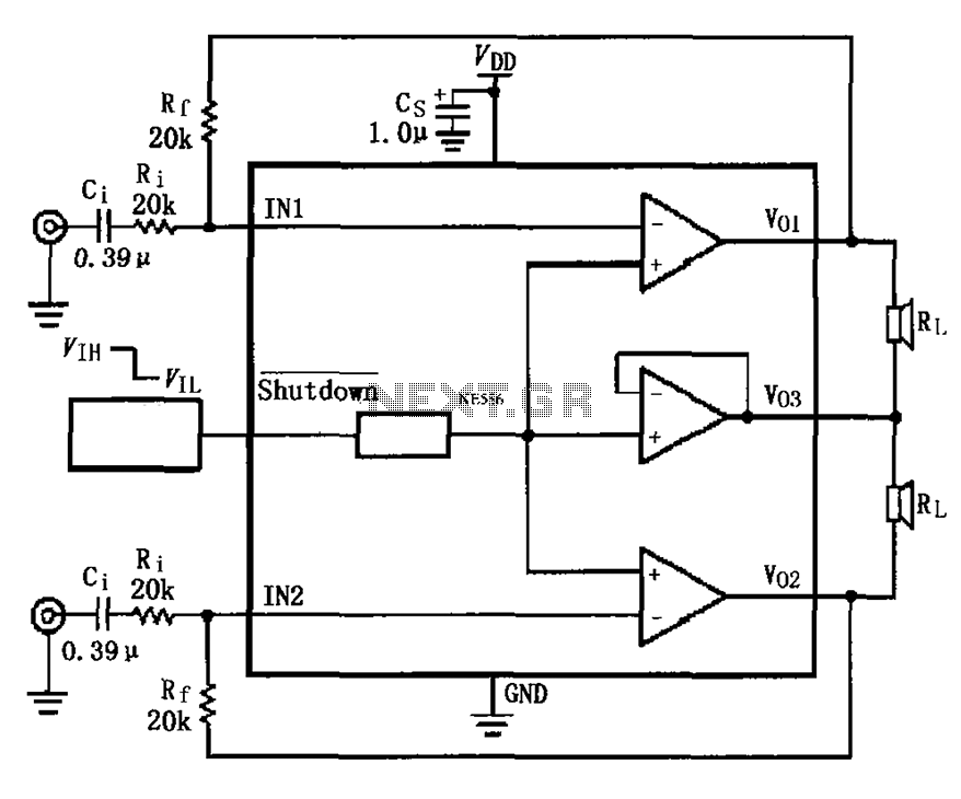
The LM4910 typical circuit is designed for a two-channel amplifier. The left and right channel audio signals are input to the LM4910 (in an MSOP/SO package) at pins 1 and 2. The output signals are delivered from pins 6,...
To comprehend the interconnections between the following circuits, it is essential to first review the concept chapter. It is at the discretion of the user to select one or two of these circuits for personal development. The discussion begins...
The delay time ranges from 0.5 to 3.5 seconds, which can be adjusted using the potentiometer RP to modify the delay duration. The circuit utilizes a timing mechanism that allows for the adjustment of delay intervals between 0.5 seconds and...
One of the critical components is a PWM speed controller, allowing for fine speed adjustments instead of just an "on" mode that runs at full power. This is important for safety. A basic stamp microcontroller was purchased, which includes...