
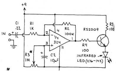
Transmitter Detector for FM Bug Surveillance

The circuit design utilizes a 9 V battery as the primary power source, making it suitable for portable applications. The core function of this circuit is to detect the presence of bugs, which typically operate within specific frequency ranges. The use of frequency modulation (FM) allows for the transmission of audio signals over varying frequencies, which can be intercepted by the circuit.
Key components likely include an antenna for signal reception, a radio frequency (RF) amplifier to boost the received signals, and a demodulator to convert the modulated signal back into its original form. The antenna captures the frequency-modulated signals emitted by the bugs, while the RF amplifier enhances the weak signals for better processing.
The demodulator, which may be implemented using a simple integrated circuit or discrete components, extracts the audio information from the frequency-modulated carrier wave. This information can then be analyzed or monitored through an output stage, which could consist of an audio amplifier connected to a speaker or a recording device.
Additional filtering components may be included to eliminate unwanted noise and improve the clarity of the detected signals. Capacitors and resistors can be used to create low-pass or band-pass filters, allowing only the desired frequency range to pass through while attenuating other frequencies.
Overall, this circuit serves as a practical solution for detecting and monitoring the activities of bugs operating within specific frequency ranges, providing valuable insights into their transmission behavior.The circuit was constructed using a few components that is powered by a 9 V battery for sensing the presence of bugs transmitting within the frequency mod. 🔗 External reference
Related Circuits
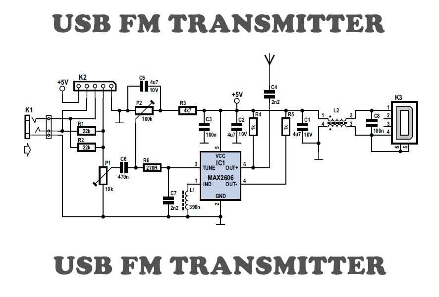
To test VHF receivers independently from local radio stations, a frequency-modulated oscillator is required, covering the range of 89.5 to 108 MHz. Building such an oscillator with discrete components is challenging. The MAX260x series from Maxim offers five integrated...
FM transmitter IC manufacturers and suppliers include FM transmitter IC manufacturers with Bluetooth capabilities. The FM transmitter features an integrated circuit with four channels. The TNA029 IR audio transmitter IC is a low-cost solution with high performance. The FM transmitter...
This circuit is a simple air flow detector that signals the presence of air flow. The sensor utilized is a filament incandescent lamp. Components include an air flow detector, a sensor, an LED, and an LM339 operational amplifier. The air...

The range of this FM transmitter is approximately 100 meters when powered by a 9V DC supply. The circuit consists of three stages. The first stage is a microphone preamplifier. The FM transmitter circuit is designed to convert audio signals...
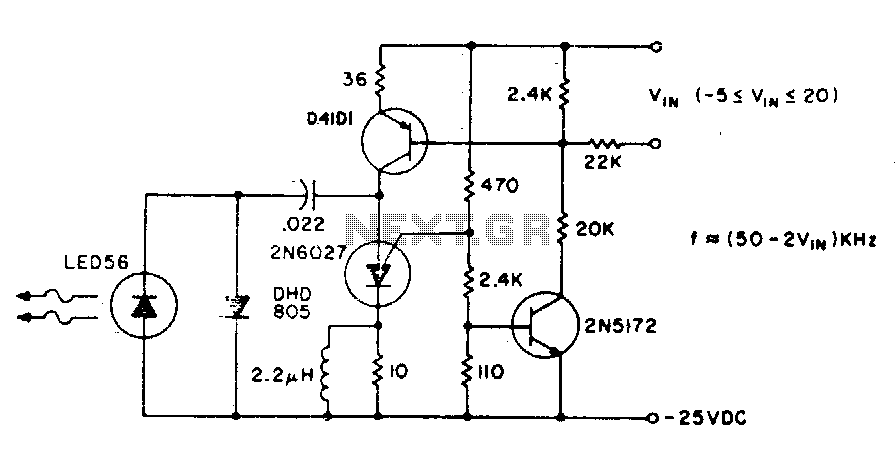
The basic circuit operates at a frequency of 80 kHz, which is constrained by the combination of the PUT (Programmable Unijunction Transistor) capacitors. The maximum modulation frequency achievable is 60 kHz. The pulse repetition rate is directly proportional to...
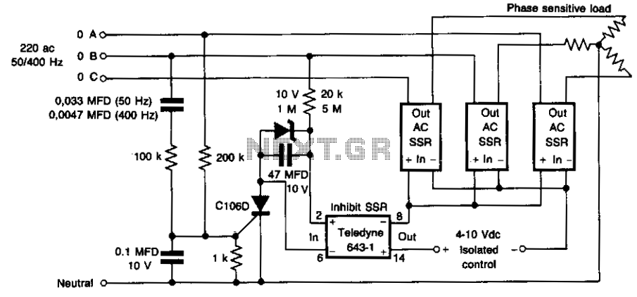
This circuit prevents damage to the load due to incorrect phasing. The three power solid-state relays (SSRs) are only permitted to turn on for a phase sequence where phase A leads phase B. If phase A lags phase B,...
Warning: include(partials/cookie-banner.php): Failed to open stream: Permission denied in /var/www/html/nextgr/view-circuit.php on line 713
Warning: include(): Failed opening 'partials/cookie-banner.php' for inclusion (include_path='.:/usr/share/php') in /var/www/html/nextgr/view-circuit.php on line 713