
Goodman Band Imaging Receiver
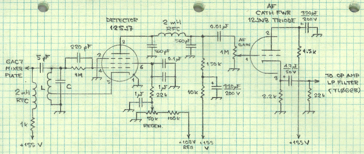
In a basic regenerative detector behind a mixer receiver with a 1.6 MHz intermediate frequency (IF), the same plug-in oscillator coil is utilized to tune the ranges of 5.4 to 10.0 MHz and 9.5 to 14.5 MHz. The oscillator coil is positioned on the low-frequency side of the signal for the higher range. This configuration not only eliminates the need for a second coil but also enhances stability at the higher frequency range. The receiver will respond to signals either 1600 kHz higher or lower than the oscillator frequency, with the unwanted response or image being filtered out by the tuning of the radio frequency (RF) circuit.
On the three lower-frequency ranges, it is possible to find two tuning spots on the variable capacitor (C1) where incoming random noise peaks. The lower-frequency peak, which requires the highest tuning capacity at C1, is the correct one, as the oscillator frequency is 1600 kHz higher than the incoming signal. Conversely, on the fourth range, the oscillator is tuned 1600 kHz lower than the incoming signal. The specific side used does not significantly impact performance, aside from calibration considerations.
The Mix-Goodman receiver concept was notably detailed in the March 1950 issue of QST, in the article "A Beginner's Four-Tube Superhet Receiver" by Don Mix, W1TS. This design aimed to minimize the cost of a first-time amateur radio station by providing coverage of two bands simultaneously (primarily 80 meters [3.5 to 4.0 MHz] and 40 meters [7.0 to 7.3 MHz]), with the potential for adding coverage of the 20-meter [14 MHz] band as an option. Unlike Grammer's simpler receiver, Mix's circuit fundamentally incorporates band imaging, allowing the receiver to cover its two main signal-frequency ranges using a single local oscillator tuning span (5.0 to 5.8 MHz). This configuration converts both bands to a relatively high 1.5 MHz IF, enabling the selection of either LO-IF or LO+IF through straightforward signal-frequency filtering.
The innovative aspect of Mix's design is that it organizes the coverage of the two bands in a sequential manner on the tuning dial, with 4.0 MHz on the 80-meter band (LO at 5.5 MHz) corresponding to 7.0 MHz on the 40-meter band. Only a retuning of the RF-input grid of the 6SB7Y converter is required to switch between the two bands. The arrangement allows for the tuning of the 80-meter amateur radio band (3500 to 4000 kHz) and the 40-meter amateur radio band (7000 to 7300 kHz) using a single 800 kHz-wide local oscillator tuning range (5000 to 5800 kHz). While this setup may seem to waste revolutions of the tuning dial on non-amateur frequencies, it effectively maximizes the use of the available tuning range for amateur radio applications.By taking advantage of certain characteristics of superhet action not normally used, it is possible with one pair of coils to cover both the 80- and 40-meter ham bands as well as ranges where commercial point-to-point c. w. and shortwave broadcast signals may be found. ”Donald H. Mix, W1TS, "A Beginner`s Four-Tube Superhet Receiver, " QST, March 19 50 CE Minimizing reception at the image frequency is fundamental to useful practical application of the superheterodyne principle ”unless the image happens to lie in another amateur radio band, and you want to receive it. This page explores the band-imaging receiver topology popularized in the 1950s by Don Mix, W1TS, and Byron Goodman, W1DX ”a design approach that uses a single local-oscillator tuning span to receive either of two bands without oscillator-tank switching, each band the image of the other.
We see its pre-echo in George Grammer, "A Two-Tube Superhet, " QST, February 1941 CE, pages 12 15 and 92: In a simple regenerative-detector-behind-a-mixer receiver with a 1. 6-MHz intermediate frequency (IF), the same plug-in oscillator coil is used to tune the ranges 5. 4 10. 0 and 9. 5 14. 5 MHz. Wrote Grammer: It will be noted that the same oscillator coil, D, is used for two frequency ranges. This is possible because the oscillator signal is placed on the low-frequency side of the signal on the higher range.
This not only avoids winding a second coil, but also gives somewhat greater stability at the highest-frequency range. . . . A word about images. The receiver will, of course, respond to signals either 1600 kc. higher or 1600 kc. lower than the oscillator frequency. The unwanted response, or image, is discriminated against by the tuning of the r. f. circuit. On the three lower-frequency ranges, when it is possible to find two tuning spots on C1 at which incoming random noise peaks up, the lower-frequency peak (the one requiring the highest tuning capacity at C1) is the right one.
The oscillator frequency is 1600 kc. higher than that of the incoming signal on these three ranges. On the fourth range the reverse is true, since here the oscillator is tuned 1600 kc. lower. Actually, it does not matter a great deal which side is used except for calibration purposes. The two-bands-for-the-price-of-one story of the Mix-Goodman receiver begins in earnest with the publication in March 1950 CE QST of "A Beginner`s Four-Tube Superhet Receiver, " by Don Mix, W1TS. Designed to keep the cost of a first-time amateur radio station down, Mix`s receiver provided coverage of two bands at a time (principally, 80 meters [3.
5 to 4. 0 MHz] and 40 meters [7. 0 to 7. 3 MHz], although coverage of the 20-meter [14-MHz] band could also be installed, and may have been added as an afterthought) without switching or unplugging any frequency-determining components. Unlike Grammer`s simple receiver, Mix`s circuit uses band-imaging as a fundamental feature: The receiver covers its two principal signal-frequency ranges with one local-oscillator (LO) tuning span (5.
0 5. 8 MHz), which converts both bands to a relatively high (1. 5-MHz) IF to allow selection of LO ’IF or LO+IF with simple signal-frequency filtering, one range the image of the other. The novelty of Mix`s implementation is that coverage of the two bands is arranged end-to-beginning on the tuning dial, with 4.
0 MHz on the 80-meter band (LO, 5. 5 MHz) corresponding to 7. 0 MHz on the 40-meter band (Figure 1). Only retuning the RF-input grid of the 6SB7Y converter is necessary to change from one band to the other. Figure 1 ”Don Mix`s band-imaging arrangement tunes the 80-meter amateur radio band (3500 to 4000 kHz, orange) and the 40-meter amateur radio band (7000 to 7300 kHz, blue) with a single 800-kHz-wide local-oscillator tuning range (5000 to 5800 kHz).
Arranging the bands end to end seemingly wastes revolutions of the set`s 6:1-reduction tuning dial on non-amateur frequencies: 4. 0 🔗 External reference
Related Circuits
In this project, you will make a simple low-power broadcast-type circuit, using a crystal oscillator integrated circuit and a collector modulated AM oscillator. You can connect the circuit to an electret microphone (pointed out in gray on the diagram)...
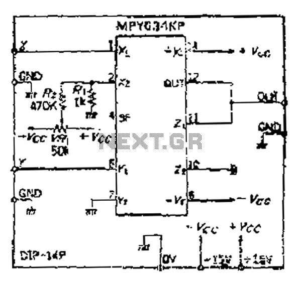
Although the inputs are differential, the right amplifier has a bias current greater than 800 nA. Therefore, the input coupling capacitor should be considered. It is important to note that the resistance value on the input side should also...
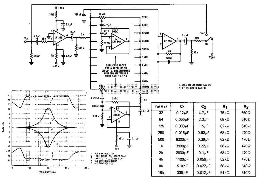
A series of active RF filters using the National LM3481C comprises a ten-band graphic equalizer. C1, C2, R1, and R2 should be at least 10% with 5% preferred tolerances. The circuit design features a ten-band graphic equalizer that utilizes a...
This is a compact three transistor regenerative general coverage receiver with fixed feedback. It's based on the principle of the ZN414 only much higher coverage. The sensitivity and selectivity is relatively good (especially on the LF and MW bands)...
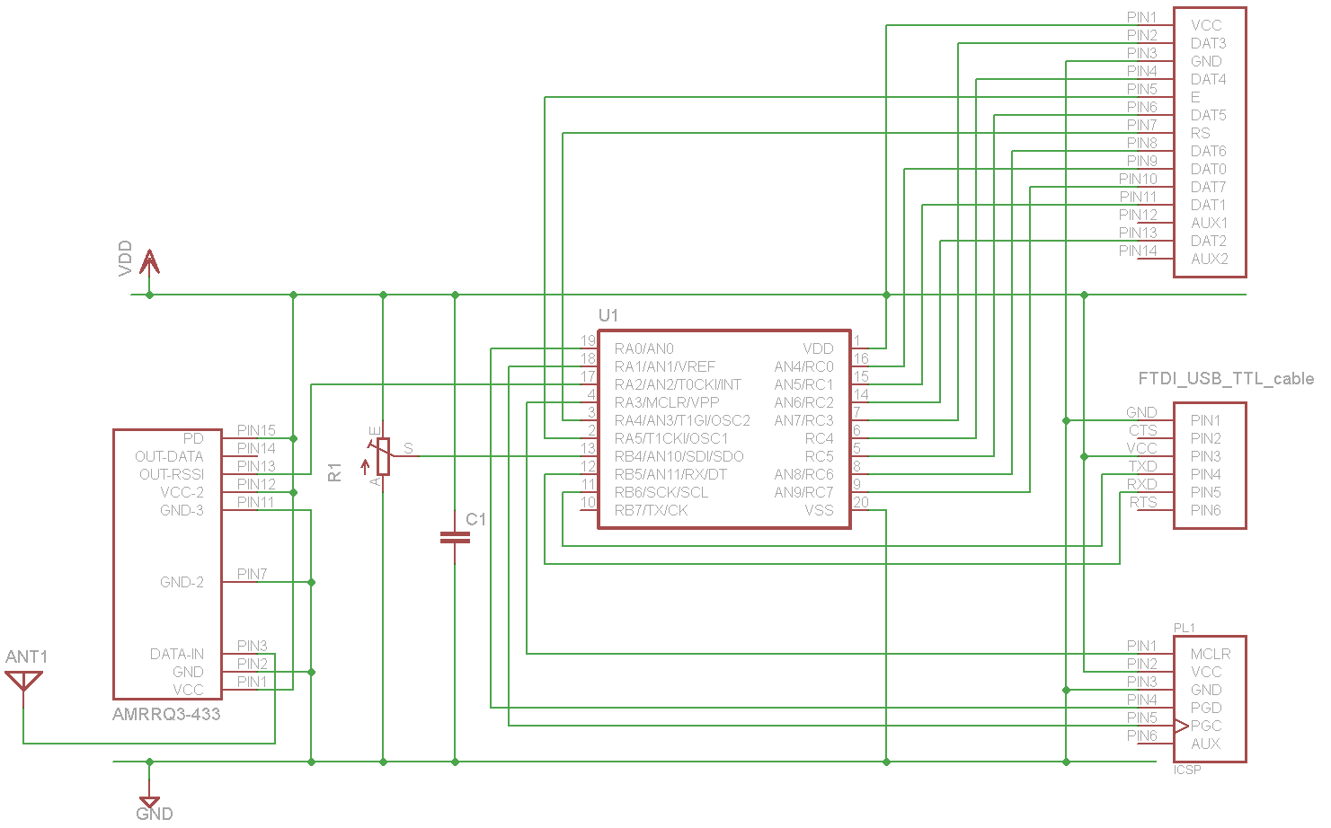
A sensor project that transmits its measurements via a 433 MHz wireless communication link. This document describes the details of a self-built receiver designed to receive data from this sensor. The objective is to create a general-purpose RF receiver...
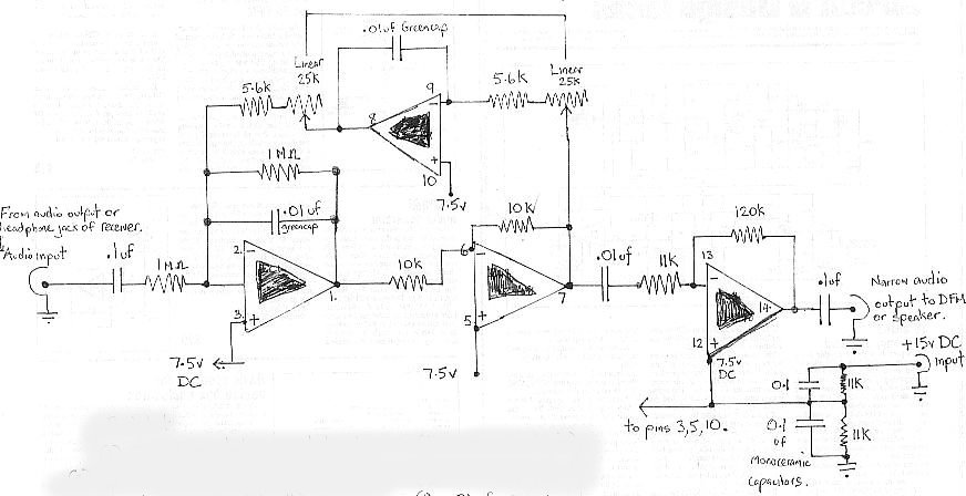
The audio bandpass filter described is beneficial for amplifying and filtering weak AM TV video carriers. For instance, a digital frequency audio multimeter (DFM) may lack sufficient input sensitivity for measuring extremely weak single sideband (SSB) TV video audio...
Warning: include(partials/cookie-banner.php): Failed to open stream: Permission denied in /var/www/html/nextgr/view-circuit.php on line 713
Warning: include(): Failed opening 'partials/cookie-banner.php' for inclusion (include_path='.:/usr/share/php') in /var/www/html/nextgr/view-circuit.php on line 713