
AM/cw 20-meter band transmitter
The circuit described is a low-power AM transmitter designed for simple audio broadcasting applications. The core component of this circuit is a crystal oscillator integrated circuit, which provides a stable frequency output. This frequency is critical for AM transmission, ensuring that the signal can be effectively received by standard AM radio receivers.
The circuit can accommodate two types of microphones: an electret microphone and a dynamic microphone. The electret microphone is preferred due to its higher output voltage, which typically exceeds the required 100mV. In cases where a dynamic microphone is utilized, the circuit may require an additional low-frequency (LF) preamplifier stage, which can be implemented using a single transistor. This stage amplifies the microphone's output to a sufficient level, allowing for effective modulation of the AM signal.
The collector modulated AM oscillator is responsible for modulating the audio signal onto the carrier wave generated by the crystal oscillator. This modulation process occurs when the audio signal varies the collector current of the transistor, thereby modifying the amplitude of the carrier wave. The output of this modulation can be transmitted through the air and received by any standard AM radio receiver, demonstrating the fundamental principles of amplitude modulation.
It is important to note that while this circuit provides a basic understanding of AM transmission, more sophisticated circuits used in professional radio stations incorporate additional components to enhance signal quality, range, and stability. Nonetheless, this simple circuit serves as an excellent introduction to the concepts of audio broadcasting and radio frequency transmission. Proper attention should be paid to the power supply and antenna design to maximize the transmission range and effectiveness of the circuit.In this project, you will make a simple low-power broadcast-type circuit, using a crystal oscillator integrated circuit and an a collector modulated AM oscillator. You can connect the circuit to the an electrec microphone (pointed out in gray on the diagram) or amplified dynamic microphone (no amplified microphone has a to low output voltage to work.
Approx. 100mv is needed). You could also add a LF preamp stage of one transistor to allow connecting a dynamic microphone directly. You`ll see that you can receive the signal through the air with almost any AM radio receiver. Although the circuits used in radio stations for AM receiving are far more complicated, this nevertheless gives a basic idea of the concept behind a princip 🔗 External reference
Related Circuits
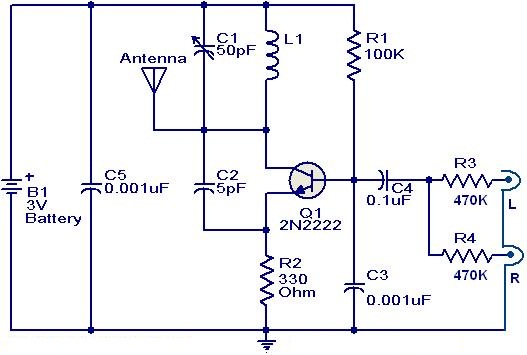
This weblog focuses on electronic circuit schematics, PCB design, DIY kits, and diagrams for electronic projects. The FM transmitter circuit utilizes the NPN transistor 2N2222. The inductor L1 and capacitor C1 generate the necessary oscillations for Q1. The collector...
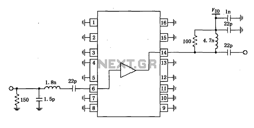
A narrowband linear amplifier circuit configured with the RF2320 operates within a frequency range of 1930 to 1990 MHz. The radio frequency (RF) signal is input from a distance of 6 feet and is amplified by an internal amplifier...
The following circuit illustrates the IC BA1404 used in a stereo FM transmitter circuit diagram. Features include ease of construction, making it accessible for anyone to build. The BA1404 is a versatile integrated circuit designed specifically for FM transmission applications....
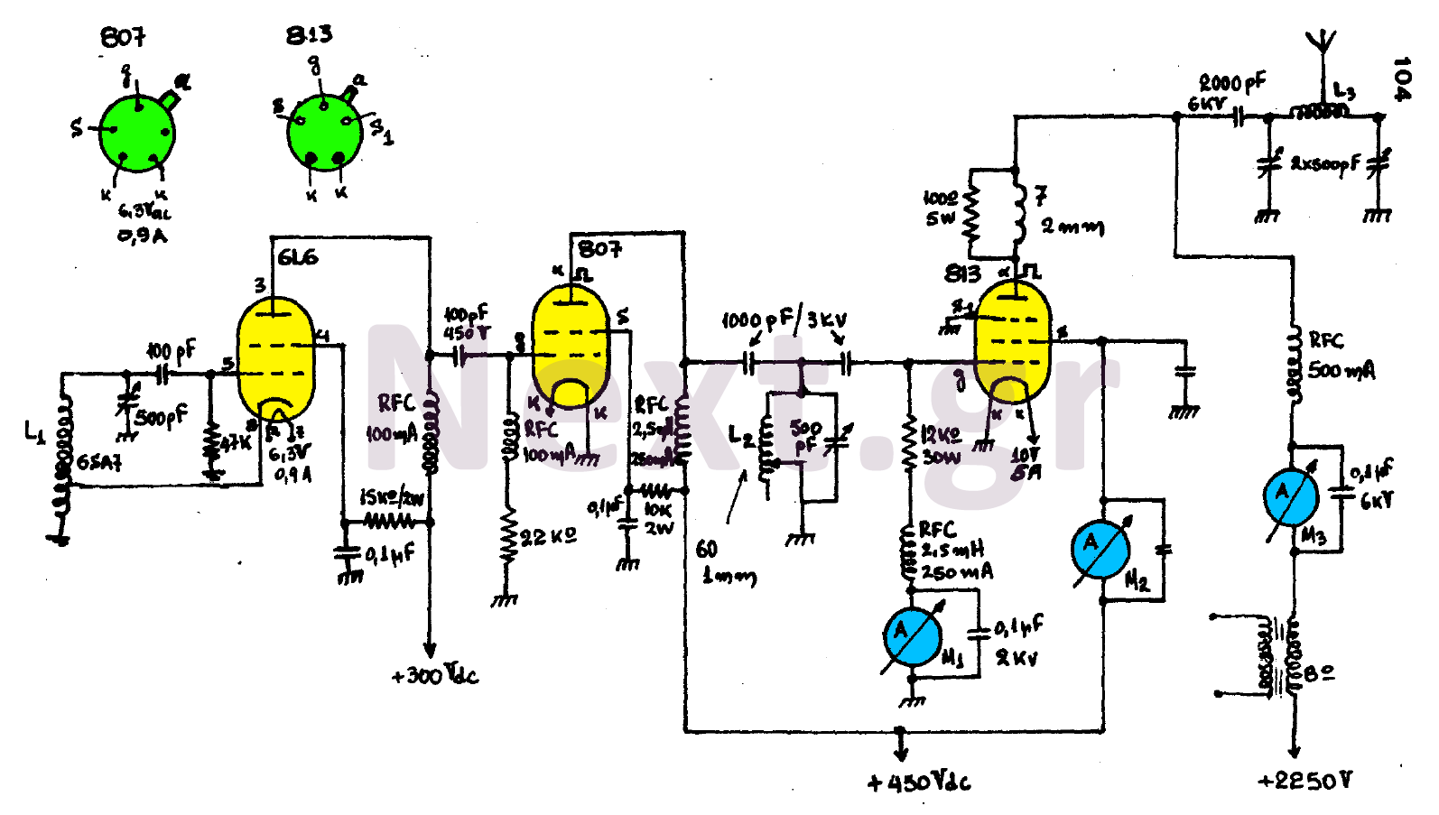
The circuit consists of three main stages and provides the antenna with a power output of 300 watts, contingent upon proper tuning. The first stage is an oscillator featuring an oscillating coil L1, which is commercially available as a...
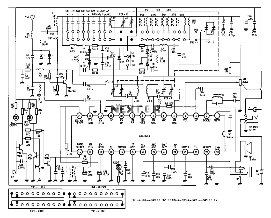
Desheng 1012 is a 12-band radio circuit diagram that covers FM, MW, SW, and TV sound frequencies. The Desheng 1012 radio circuit is designed to receive a wide range of frequencies across multiple bands, including FM (Frequency Modulation), MW...
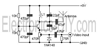
This is a simple video transmitter capable of transmitting signals up to 50 meters. It can be connected to a camera or other video sources, allowing viewing on a VHF channel analog TV. The transmitter operates on a supply...