
Telephone amplifiers
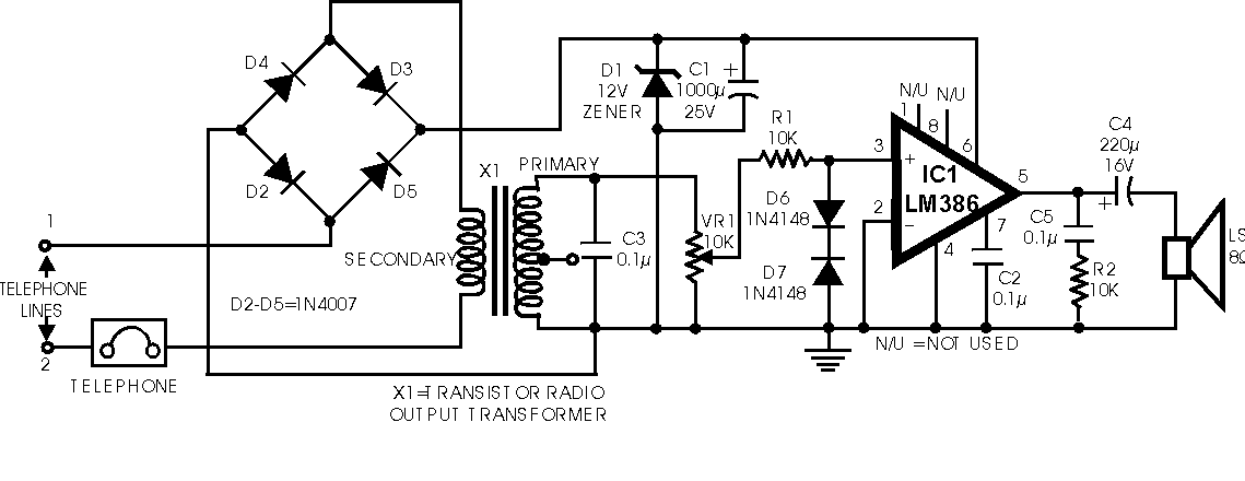
The proposed telephone amplifier circuit enhances call clarity by amplifying the audio signal received from the telephone line. The core component, IC LM386, is a low-voltage audio power amplifier capable of delivering up to 1 watt of output power, making it suitable for small audio applications such as this. The design incorporates a simple yet effective volume control mechanism through potentiometer VR1, allowing users to adjust the loudness to their preference.
Diodes D6 and D7 are critical in protecting the circuit from excessive input voltage, ensuring that the signal does not exceed ± 700 mV, which could potentially damage the IC. The use of a transformer, specifically a transistor radio output transformer, is innovative; it allows the circuit to leverage the speech signals' magnetic properties to induce an audio signal. This method efficiently utilizes existing components to create a functional and cost-effective solution.
The bridge configuration of diodes D2 through D5 provides essential polarity protection, allowing the circuit to operate correctly regardless of the orientation of the telephone line connection. This feature is particularly useful in varying installation scenarios where line polarity may not be consistent.
For testing purposes, the circuit can be powered using a 6-volt supply, with audible feedback such as a hissing sound indicating functionality. The introduction of 6V AC allows for further testing of the amplifier's performance through the audible hum, which can be manipulated by adjusting the volume control. This comprehensive design offers a practical solution for improving telephone communication quality, particularly in environments where background noise may hinder clarity.While talking to a distant subscriber on telephone, quite often we feel frustrated when the voice of the distant subscriber is so faint that it is barely intelligible. To overcome the problem, circuit of an inexpensive amplifier is presented here. It can be assembled and tested easily. There is no extra power source needed to power up the circuit, as it draws power from the telephone line itself. The amplifier will provide fairly good volume for the telephone conversation to be properly heard in a living room. A volume control is included to adjust the volume as desired. The circuit is built around IC LM386. Diodes D6 and D7 are used to limit the input signal strength. Transformer X1 is a transistor radio`s output transformer used in reverse. As original secondary (output) winding is connected in series with the telephone lines, the speech signals passing through the lines cause change in the magnetic flux in the core of transformer and thereby induce signal voltage across the primary winding.
This audio signal is used as input for IC LM386. Diodes D2 through D5 connected in bridge configuration constitute a polarity guard so that the amplifier is powered with correct polarity, irrespective of the line polarity, Zener diode D1 may have any breakdown voltage between 6 and 12 volts range. e. The circuit can be easily tested by connecting a 6 volts supply to line terminals 1 and 2. A hissing sound will be heard from the loudspeaker. Now connect 6V AC from a transformer to terminals 1 and 2 and observe hum in the loudspeaker. The volume of the hum can be changed through potentiometer VR1. Diodes D6 and D7 limit the input below ± 700 mV. 🔗 External reference
Related Circuits
The amplifier in question is comparable to another model that has a lower parts count. It is worthy of construction. The amplifier under discussion features a simplified design that maintains high performance while reducing the number of components required for...
This project has been specially designed to introduce you to SMD (Surface Mount Devices). Surface Mount is really not new. It started as far back as 1940 with a hybrid circuit in a digital watch. A chip was cemented...
Preamps may in some cases use a simple regulator, with the supplies taken from the main amp power supply. This can be a problem if the main amp is of very high power, as the supply voltage will be...
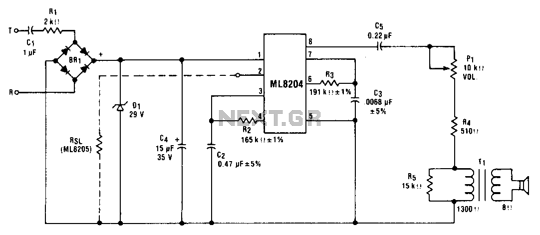
This circuit utilizes ML8204/ML8205 devices. The components illustrated result in an output frequency that oscillates between 512 Hz (fin) and 640 Hz (fb) at a modulation rate of 10 Hz (t). The circuit employing ML8204/ML8205 devices is designed for frequency...
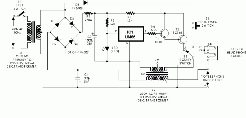
Here is a circuit of an offline telephone tester which does not require any telephone line for testing a telephone instrument. The circuit is so simple that it can be easily assembled even by a novice having very little...
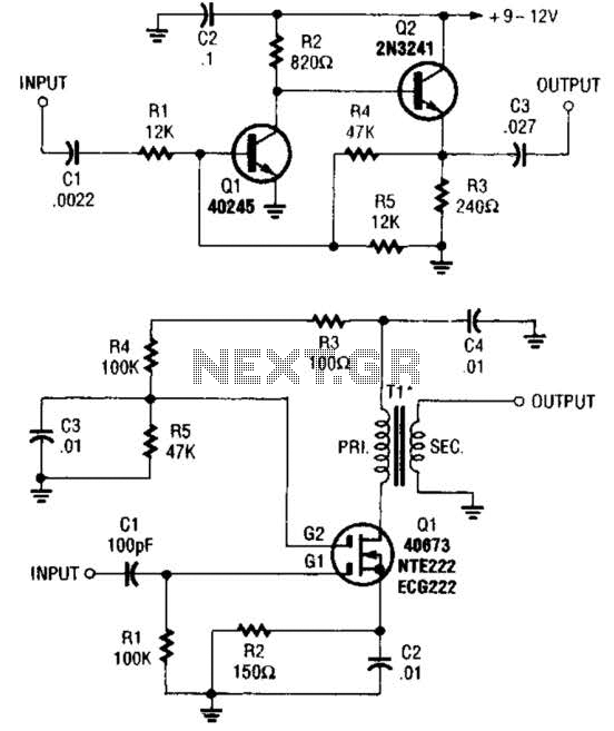
These two buffer/amplifiers have been effectively utilized with variable frequency oscillators (VFOs): one (depicted in A) is constructed using a pair of bipolar NPN transistors, while the other (illustrated in B) is designed around a dual-gate MOSFET. The first buffer/amplifier,...