
grundig 5040w3d circuitry analysis

The described circuit involves a first IF transformer with a primary winding that serves as an inductive coupling without a capacitor, indicating a design choice that simplifies the tuning process. The coupling mechanism allows for efficient signal transfer from the FM tuner to the first IF stage while maintaining a balanced transmission line, which is crucial for minimizing signal loss and reflections. The characteristic impedance of the twisted pair is a critical parameter, as it ensures that the system operates optimally by matching the load to the source.
The adjustable ferrite core within the first IF transformer enables fine-tuning of the inductance, which is essential for achieving resonance. This resonance condition is critical as it transforms the impedance characteristics of the circuit, allowing the coupling coil to function effectively. The termination of the twisted pair with a resistor matching the characteristic impedance is a standard practice to prevent signal reflections, which can degrade performance.
The interaction between the coupling coil and the anode circuit of the ECC85 is significant, as it impacts the overall Q factor of the circuit, thereby influencing the bandwidth and selectivity of the tuner. The final adjustment of the coil ensures that the entire assembly operates within the desired specifications, thereby enhancing the quality of the received signal. The consideration of reactive components in the circuit underlines the complexity of RF design, where both inductive and capacitive elements play vital roles in circuit behavior at resonance. This comprehensive understanding of the circuit's operation is essential for optimizing performance in high-quality FM tuner designs.On the primary winding of the first IF transformer there is no capacitor. Does that mean it has only one tuned circuit, and the primary coil is just an inductive coupling The routing of the twisted pair couldn`t be done exactly the same every time. Was it necessary after assembly of the complete set to readjust the coil in the tuner (at the anode of the second section of the ECC85),
or was it sufficient to simply adjust the first IF transformer I`m looking forward to lively participation. Whoever doesn`t have access topost in this forum is welcome to send me (Thomas G. or Tom A. )questions by email. [To send an email to me (Tom A. ), click on "mail to the author" at the bottom of this thread. To send an email to Thomas G. , go the the German_thread and click on "mail to the author" at the bottom of the first post. ] The twisted pair transmission line between the FM tuner and the first IF stage is twisted so that it can serve as a balanced (symmetric) transmission line with nearly constant impedance.
The characteristic impedance is determined by the diameter of both wires and their distance from one another (in this case, the thickness of the insulation times two). The first IF transformer, which has only one adjustable ferrite core, I would assume has its primary and secondary winding tightly coupled, so thatthe primary capacitance is transformed to the secondary.
The primary winding is necessary in order to couple the balanced feed line (the twisted pair) to the unbalanced grid circuit of the first IF stage. Therefore a transformer with a single tuned circuit and a coupling coil is used. Given that the FM tuner was previously aligned, no additional readjustment of the output circuit of the ECC85 in the tuner is necessary after final assembly.
For the previous alignment of the tuner, it would be sufficient to terminate the end of the twisted pair with a resistor matching the characteristic impedance of the transmission line. Your answer is also accepted. As can be seen in the following text, it`s a matter of how you see things with respect to the question: Since it was previously aligned, does get get aligned again or not The inductance of the coupling coil, however, is affected by the position of the adjustable core in the IF transformer, and the position of the core in turn depends on the capacitance of C67, the wiring, and the next tube.
For top-notch performance, a final adjustment of the coil in the FM tuner box is necessary, and was actually done. As you have shown, the feedline to the first IF transformer and the coupling coil in series with it form part of the inductance of the anode circuit of the ECC85.
If the first IF transformer is tuned to resonance it becomes a purely ohmic impedance (a pure resistance), and as a result, this is true of the coupling coil too. Therefore the feedline is terminated with a matched resistive load. Therefore, the termination resistance, which is created by the coupling coil and which matches the characteristic impedance of the transmission line means that there will be no relectinos on the twisted pair.
In this case, the feedline simply looks like its characteristic impedance, and this R is in series with the anode coil of the ECC85. If all of this is correct, then the twisted pair simply affects the Q of the anode circuit and increases its bandwidth.
Of course it`s clear to me, that for a high quality product, the tuner would be adjusted as part of a final alignment. Therefore I didn`t understand the question by Herr GG nzel. Only the parallel circuit as a whole becomes ohmic at resonance. Each of its components continues to behave as a capacitance or a (damped) inductance. In particular, a rather large reactive current flows between the C and L, because of the increased voltage at resonance.
Therefore I view the complete combination of the transmission line and coupling coil as an inductance, which together with the adju 🔗 External reference
Related Circuits
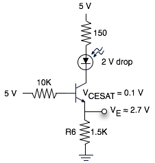
The schematic represents a relatively simple transistor circuit. Analyzing such schematics evokes memories of college days spent studying electrical engineering. However, the complexity of the schematic can be daunting after a long time away from the subject. To refresh...
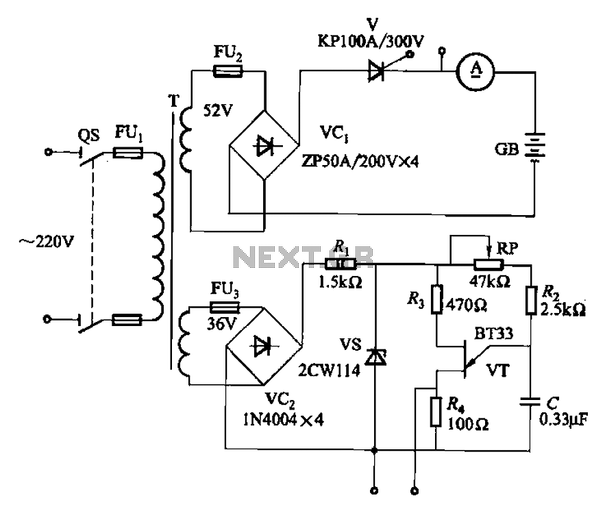
The adjustment potentiometer RP can modify the magnitude of the DC output voltage. The adjustment potentiometer, designated as RP, is an essential component in various electronic circuits, particularly in power supply systems and signal conditioning applications. It serves as a...
The search loop can be constructed in various ways; however, the method presented here should provide a solid foundation. Refer to Fig. 2 as a guide for assembling the loop. The loop should be made from non-metallic and moisture-resistant...
The yellow wires on the far right serve as temporary power connections, allowing battery power to enter through the contact studs located in the large holes that press against the radio's battery terminals. The cable in the lower right...
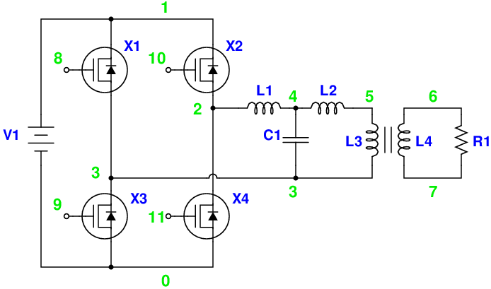
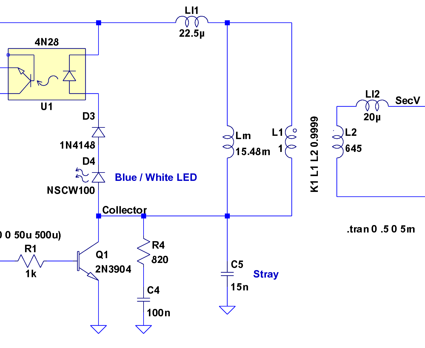
Magic Sinewave Analysis using SPICE and a Simple Inverter Circuit. This document discusses the analysis of a sinewave signal generated by a simple inverter circuit using SPICE simulation software. The inverter circuit is designed to convert a DC input voltage...
This application note explains how the transfer function of most operational amplifier circuits can be derived through a straightforward process of nodal analysis. The transfer function of operational amplifier (op amp) circuits is a critical aspect for understanding their behavior...