
GS500 Horn
The relay circuit functions as a critical component in controlling high-power devices within automotive systems. By utilizing a low-power input to control the relay coil, significant current can be managed safely. The relay acts as an intermediary, allowing the horn to operate without directly subjecting the horn button or wiring to high currents, which could lead to overheating or failure.
The integration of the relay into the horn circuit not only enhances the reliability of the horn operation but also allows for the use of horns that require higher power levels than what the standard wiring can handle. The choice of horn, such as the Stebel Magnum or HF80 discs, depends on the desired sound output and available installation space.
When constructing the mounting bracket, attention to detail is essential to ensure that the horns are securely fastened and positioned for optimal sound projection. The use of aluminum for the bracket provides a lightweight yet sturdy solution that can withstand the vibrations and environmental conditions typical in automotive applications.
In summary, the described relay installation enhances the functionality of the vehicle's horn system, providing improved sound output and reliability while ensuring that the electrical components are protected and operate within safe parameters. Proper wiring practices, including the use of fuses and secure connections, are paramount for long-term performance and safety.A relay is essentially an electrically operated switch it has a coil that uses magnetism to close the contacts on the switch. In automotive terms 12V running through the coil will allow 12V to run through the switch contacts. So why is a relay useful You can use a low-power source to energise the coil to switch power to a high-power device (lik
e a horn!) The circuit diagram below shows the installation of a relay into the existing horn setup. All the existing circuit is shown in black, and the new addition is shown in blue. You want to disconnect your existing horn and connect its wires to the coil of the relay. This means that when you press the horn button it will provide power to the coil. You want to connect one of the switch connections of the relay to the positive side of your battery - with its own wire and fuse (you are essentially creating a new fused circuit for your bike). The other relay switch connection wants to be connected to your new horn(s). The remaining connection on your horn needs to be run back to the negative terminal on your battery to complete the circuit.
Some relays come with an in-built fuse holder (which saves work, left), but a separate fuse holder would also be fine. You can also get pre-wired bases (right), or you could use spade lugs. The Stebel Magnum is an electromagnetic horn that puts out 136dB (at 4 inches, 112 @ 2m) from 6A of current.
It is available in 500 and 410Hz. It can be easily mounted underneath the bottom triple on F-models, or inside the side fairing. Due to its size it is not particularly suited to E-models without looking like a glaring addition. (shown above next to a stock-sized horn) You can achieve the same volume as the Magnum by using 2 HF80 discs. They come as a dischordant pair, emitting 340 and 430Hz from 9A combined. Due to their smaller dimensions these could be installed easily using the existing horn mounting point, but they will be clearly visible as an addition.
A better option is to mount them on the front of the bike frame under the oil cooler, using a bracket fashioned according to the dimensions below. I used 3x25mm aluminium strip bent in a bench vice. This then attaches to the bracket that supports the underside of the oil cooler. Install the horns in your aluminium bracket, hold it in the correct position, and scribe with a pencil the edges of each bracket on eachother.
Then when you come to take the oil cooler bracket and your new horn bracket off these pencil lines will allow you to get them correctly aligned on the drill press for drilling. I used a pair of 3mm bolts to hold them together. A touch of satin black spray-paint will make your new bracket look like it came from the factory. Install the horns to the bracket and the bracket to the oil cooler bracket. Then it`s time to wire up your wiring and relay as per the circuit diagram above. 🔗 External reference
Related Circuits
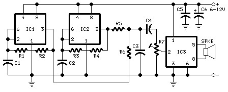
The following diagram is the schematic diagram for a car horn circuit, which can be utilized for car modifications. Components List: R1 = 68K, R2 = 2K2, R3 = 56K, R4 = 3K3, R5, R6 = 4K7, R7 =...
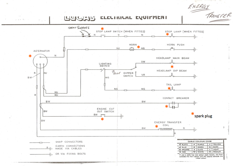
Timed precisely with the pistons' pumping, this component works with the ignition coil to create the voltage jump that causes the spark in the spark plug. The engine cut-out switch serves as an emergency button; when pressed, it provides...
The main power supply to the system must be a regulated 12 volts DC with a minimum input from the train control AC or DC power supply of 13.5 VAC connected to pos 3 and 4 of the rectifier...

This circuit is a module for a diesel and horn train system. It is constructed using a 555 timer IC and several operational amplifiers (op-amps). The circuit serves as a complete system for the horn function. The main power...
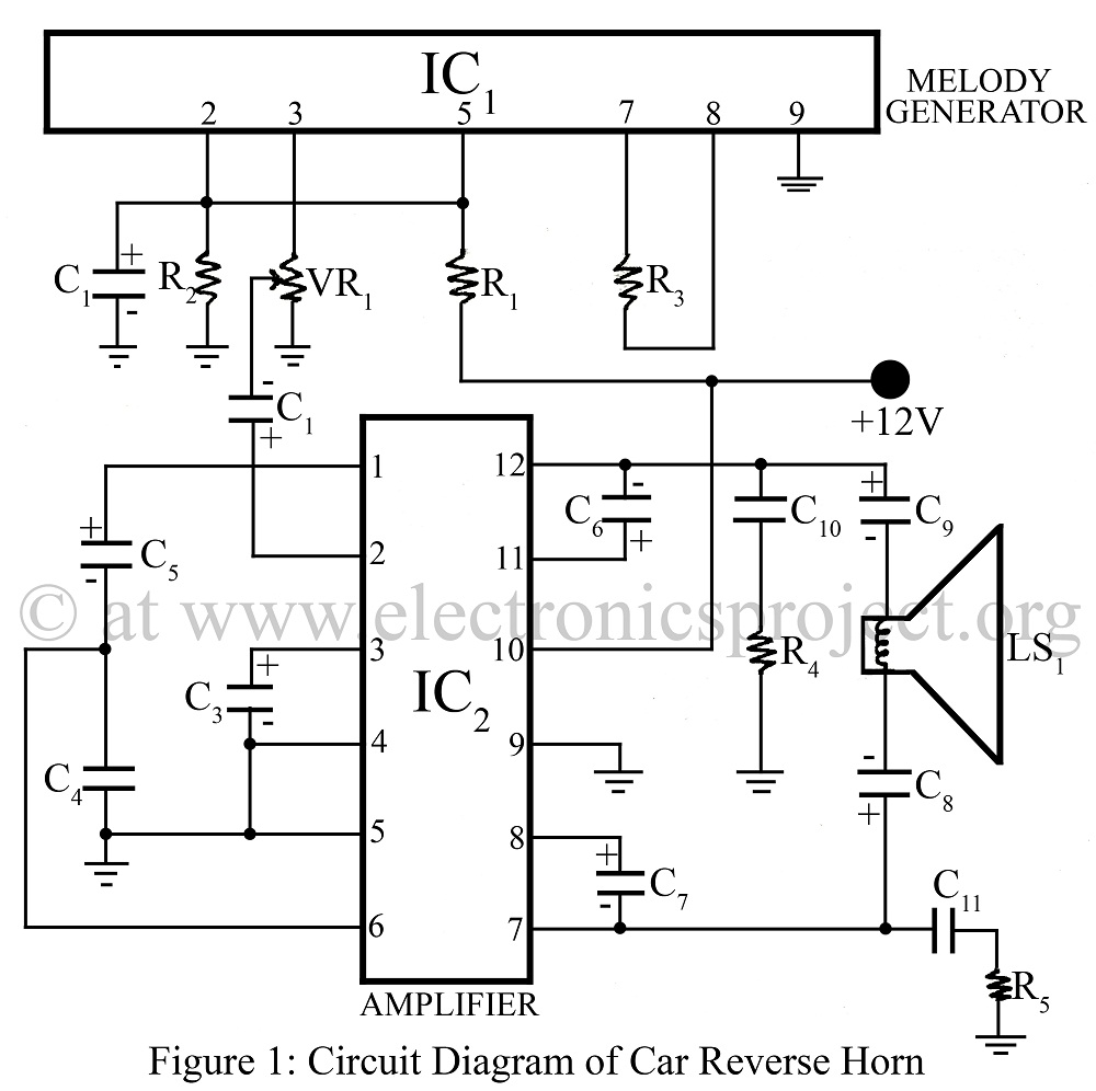
The Car Reverse Horn is a circuit designed for use in vehicles, utilizing a melody generator integrated circuit (IC) CTC2877 in conjunction with an amplifier IC AN7148. This circuit diagram facilitates the implementation of a reverse horn system in...
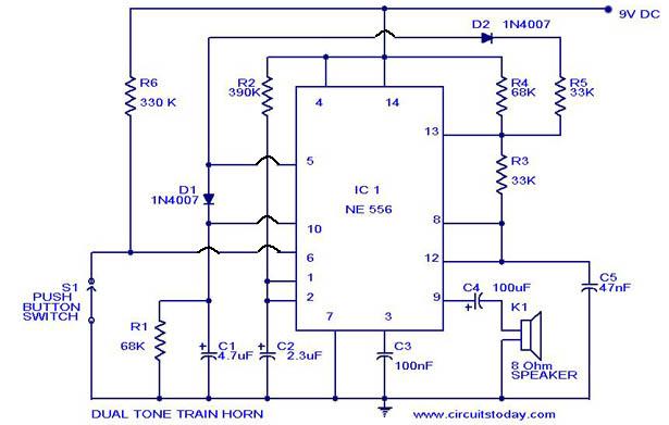
A dual-tone model train horn/sound generator/simulator circuit can be created using two NE 555 timers connected in cascade. However, the circuit diagram presented is designed with the NE 556 integrated circuit, which essentially comprises two 555 timers in a...