
GSM Automatic Meter Reading
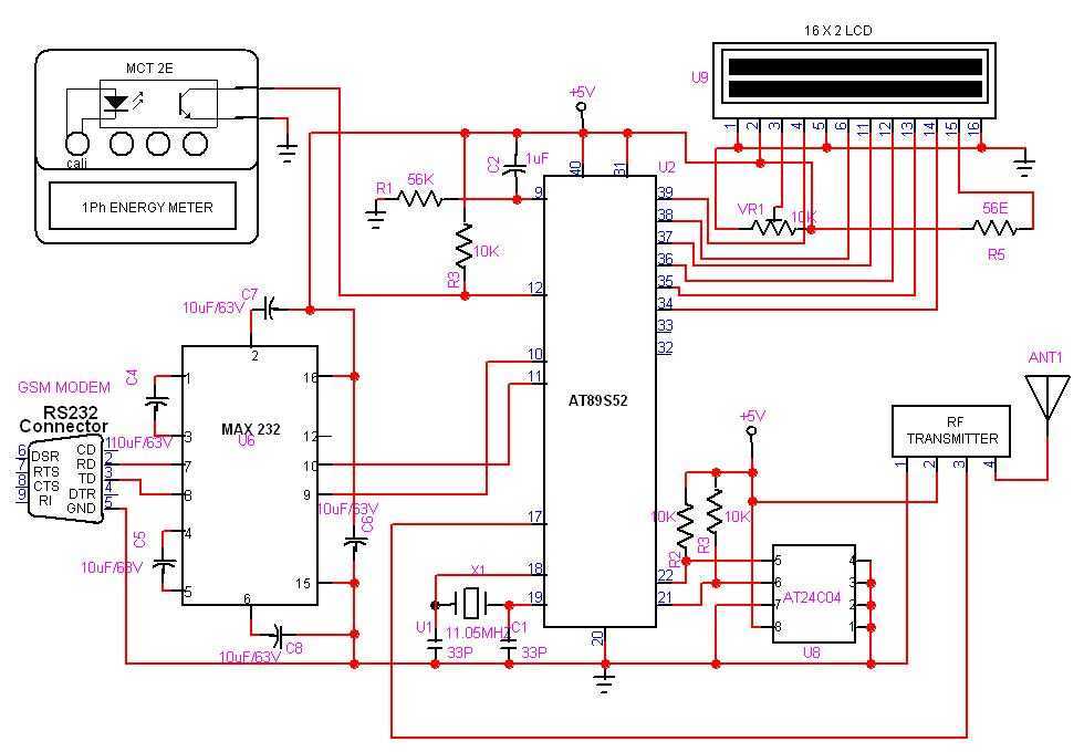
The GSM-based Automatic Meter Reading (AMR) system is designed to facilitate the efficient collection and transmission of energy meter data. The core of the system consists of a transmitter that interfaces with the energy meter. This transmitter is responsible for counting the electrical pulses generated by the meter, which correspond to energy consumption. The counted data is then displayed on an LCD screen for immediate visual feedback.
In addition to local display, the transmitter is equipped with a radio frequency (RF) module that enables wireless transmission of the counted data to a receiver module connected to a personal computer (PC). The receiver captures the RF signals and decodes the transmitted data, allowing the PC application to present the meter readings in a user-friendly format. This setup allows for real-time monitoring and analysis of energy consumption without the need for manual reading.
To enhance the functionality of the system, a GSM modem is integrated into the kit. This feature allows users to retrieve meter readings remotely by calling a designated phone number. Upon receiving the call, the microcontroller identifies the caller's mobile number, disconnects the call to avoid any charges, and subsequently sends back the current meter readings via SMS. This functionality ensures that users can access their energy consumption data at no cost, promoting convenience and accessibility.
The overall architecture of the AMR system consists of several key components: the energy meter, pulse counting transmitter, LCD display, RF transmission module, receiver module, PC application, and GSM modem. Each component plays a vital role in ensuring seamless operation and data integrity, making this AMR system a comprehensive solution for modern energy management.GSM based Automatic meter reading, or AMR, is the technology of automatically collecting data from energy meter and transferring that data to a central database for billing and/or analyzing. The Transmitter is connected to the meter and it counts the pulses from it and displays it over the LCD display.
It also transmit the data over RF to the PC. At the receiver end the data is received by an receiver module and the PC application will display it over the PC. An GSM modem is also connected to the kit so that anybody can call to the number and get back the Meter readings as SMS. The meter reading can be obtained at zero cost. Since the microcontroller will get the mobile number and disconnect the call so the user wont get any charge for the call.
Later the microcontroller will send back the meter readings to the called number as SMS. 🔗 External reference
Related Circuits
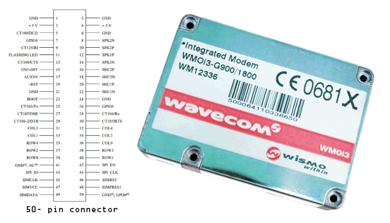
Modems are devices that connect remote devices to a computer or enable communication between multiple computers. While traditional modems typically use wired connections, the GSM modem described here operates wirelessly. It can link two computers, connect a computer to...
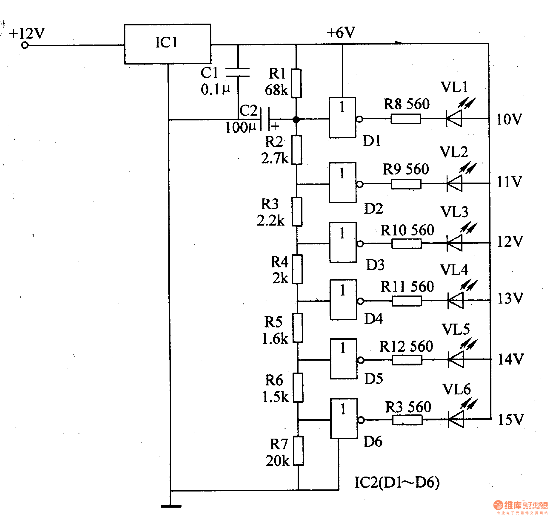
The LED car voltmeter comprises a filter circuit, a voltage distribution filter circuit, a voltage amplifier circuit, and an LED display circuit, as illustrated in Figure 7-77. The regulator filter circuit includes a 3-terminal IC (IC1) and a filter...
This circuit is designed for precise centigrade temperature measurement. It features a transmitter section that converts the sensor's output voltage, which is proportional to the measured temperature, into frequency. The output frequency bursts are transmitted through the mains supply...
This circuit functions as a simple optical level indicator for sound signals, adaptable to various user needs. It allows for adjustments to input levels via trimmer potentiometers TR1 (Level) and TR2 (Gain). The signal is then rectified by diodes...

The SD card can communicate using three different transfer modes: 1-bit SD mode, 4-bit SD mode, and SPI mode. According to Wikipedia, all cards must support all three modes, except for micro SD cards where the SPI mode is...
Automatic color holiday lights circuit The automatic color holiday lights circuit is designed to control the operation of decorative lights during festive seasons. This circuit typically utilizes a microcontroller or a timer to manage the sequencing and color changes...