
vu meter 1

This circuit operates by monitoring the amplitude of sound signals and converting them into a visual representation through an array of LEDs. The input sound signal is first received and passed through a level adjustment stage, where the user can fine-tune the input sensitivity using the trimmer potentiometers TR1 and TR2. TR1 adjusts the input signal level, while TR2 controls the gain, allowing for precise calibration based on the sound environment.
Following the adjustment, the signal is rectified using diodes D1 and D2. These diodes are configured to allow only the positive half-cycles of the AC signal to pass, effectively cutting off the negative portions that do not contribute to the signal level indication. The rectified output is then fed into the main indicator circuit, which consists of a series of diodes (D3 to D13) and transistors (Q2 to Q13). The transistors serve as switches that control the current flowing through the LEDs based on the rectified signal's amplitude.
The LED array (LD1 to LD13) visually represents the sound signal level. Each LED is designed to turn on when the rectified voltage reaches approximately 0.65V, providing a clear visual cue of the signal strength. The design allows for scalability; additional LEDs can be added to the circuit as needed. However, it is crucial to recalculate the total current requirements to ensure that the power supply can adequately support the additional components without exceeding the rated current of 100 mA for the entire indicator circuit.
Overall, this optical level indicator circuit is versatile and can be tailored to various applications, making it suitable for different user requirements in sound signal monitoring.It is a simple circuit of optical index of level of sound signals, adapted in various needs of user. It can be adapted in various levels of entry, regulated from trimmer TR1 (Level) - TR2 (Gain), then it is rectified by the D1-2 (cutting off of negative periods of signal-rectification) and drived to the main circuit of index, that it is constitute d by D3. D13, the transistors Q2-Q13 and the materials that exist around them. The optical index him we take from the line of LED LD1-13. The each led turns on when the level is altered at 0, 65V roughly. The requirements in current are 100 ma with complete index. We can add all units LED we want, always calculating the current where they will need the news LED. 🔗 External reference
Related Circuits
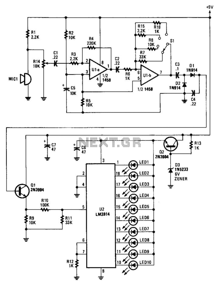
An electret microphone feeds an audio amplifier/rectifier combination. The amplifier has switchable gain. The rectifier output drives an LM3914 bar-graph generator. R14 provides fine gain control. The circuit begins with an electret microphone, which serves as the primary audio input...
In this circuit, a simple calculator, in conjunction with a COB (chip-on-board) from an analogue quartz clock, is used to make a telephone call meter. The calculator enables conversion of STD/ISD calls to local call equivalents and always displays...
The circuit for the Celsius thermometer depicted in the diagram is based on the well-known LM334 type from National Semiconductor. This integrated circuit (IC) functions as a sensor that outputs a current directly proportional to the temperature in Kelvin...
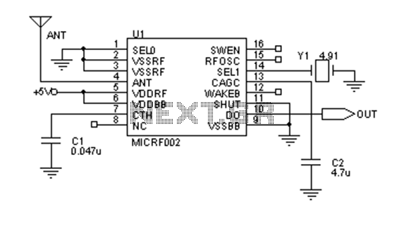
Early transmitters using LC oscillators experience significant frequency drift. The introduction of Surface Acoustic Wave (SAW) devices addresses this issue, providing substantial frequency stability comparable to crystals. These devices can achieve fundamental frequencies in the hundreds of megahertz or...

This is a simple design of an audio level meter. The circuit utilizes a single integrated circuit (IC) and a minimal number of external components. It is based on the LM3915, which functions as the controller for the audio...
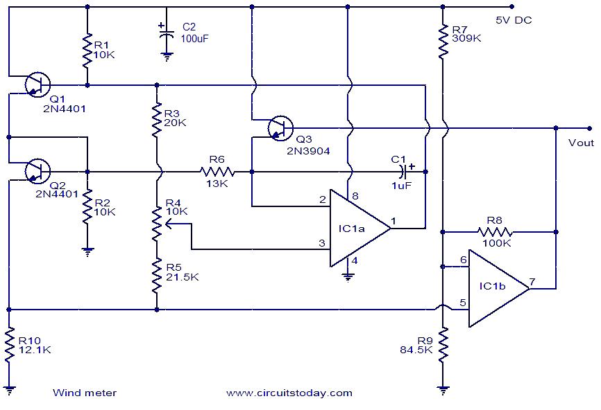
This is a simple wind meter (anemometer) circuit. While accuracy cannot be guaranteed, the circuit functions adequately. It can measure wind speeds up to 75 m/s. Transistors Q1 and Q2 are employed for wind sensing, utilizing the relationship between...