
GSM modem circuit with Wavecom WMOi3
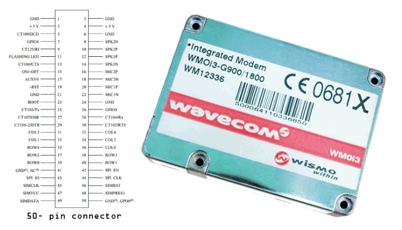
The circuit construction is relatively straightforward. It consists of a closed module based on the Wavecom model WMOi3 integrated modem, which operates on two frequency bands: E-GSM 900 and 1800MHz, adhering to Class 4 (2W at 900MHz) and Class 1 (1W at 1800/1900MHz). The exterior features a plug for antenna connection and a dual bar for all necessary connections. Proper string matching is essential to connect the modem to a computer. The module requires a 5V, 1A power supply to function.
Typical consumption is 300mA in GSM 900 mode at 2W, while standby consumption is only 9mA. The output and input RS232 lines operate at 3.3V levels. These levels can be adjusted to meet the voltage requirements of the RS232 interface using the integrated MAX3238 when connecting to a personal computer. However, if the modem is interfaced with an external microcontroller circuit, the microcontroller must operate at 3.3V for compatibility.
Implementing the modem is a relatively simple task. The necessary board is shaped appropriately, and bridges must be constructed as indicated in the accompanying figure. Care should be taken to avoid excessive soldering; the solder joints must be small and not too high to prevent short circuits. The primary challenge in construction lies in affixing the double string to support the module.
The contacts of the strings are spaced closer together than those of an integrated circuit, specifically at 2.54mm. Additionally, the strings are located on the printed side of the board, while the module is positioned on the copper side. An insulating layer of plastic should be inserted between the module and the board.
This arrangement may complicate circuit control. Prior to operating the circuit, a thorough inspection of the entire assembly for short circuits is necessary. After ensuring there are none, the board should be checked multiple times. The modem board connects directly to the MAX3238 board, with each row linked to the corresponding opposite row, ensuring proper communication and functionality within the circuit.Modems are devices that connect either remote devices to a computer, or two or more computers to each other. Their connection is usually wired. The GSM modem we present is wireless. It can connect two computers, a computer with the internet or even be the central unit for a data acquisition system.
Generally the construction is a GSM phone without keys and display. Its operation is easily accomplished by its serial door with AT commands. The serial port connects a personal computer, a laptop or a microcomputer. The modem and computer set creates a unit on a network. This system can be portable and at the same time have access to other computers or terminal devices. Suppose that this system is responsible for collecting meteorological data, whenever there are some reasons, the computer will pick up a phone from the cell phone and send the data to any internet address or simply to a printer in your office a lot Kilometers away. Modern GSM is another device that allows you to expand your network or start a new application that you would hardly start with.
The circuit of construction is relatively simple. The whole construction is a closed module of the wavecom model WMOi3 integrated modem. It works on two bands E-GSM 900 and 1800MHz and obeys Class 4 (2W 900MHz) and Class 1 (1W 1800 / 1900MHz). Outside, it has a Plug for connecting the antenna and a double bar where all the connections will be made.
String matches are the necessary data to connect to a computer. The module to work needs a 5V and 1A power supply.
The average consumption is 300mA in GSM 900 and 2W. In standby, it consumes only 9mA. Output and input RS232 lines have reasonable levels of 3.3v. These levels can get the voltage levels that the R5232 wants with the integrated MAX3238 if we are going to connect the construction to a personal computer.
But if we combine the modem with an external microcontroller circuit, the microcontroller should work at 3.3v for compatibility reasons.

Construction
Implementing the modem is a relatively simple matter. The necessary board is in the shape. On this board we will make the bridges shown in the following figure. Here we must be careful not to overdo it. Welds should be small and not too high. At the same time, there should be no short circuits due to welding or other cause. The difficulty in construction is in the gluing of the double string to support the module.
The contacts of the strings have a shorter distance than the terminals of an integrated one, ie 2.54mm.
Additionally, the strings are located on the printed side. The module is finally placed on the same side as copper. Between the module and the board an insulating surface of some plastic must be inserted.
This placement results in difficulty in controlling the circuit. Before putting the circuit in operation, carefully examine the whole block for any short circuits. When you make sure it does not, then check again and again the plaque again, once again. The modem board connects directly to the MAX3238 board. Each row is connected to the one opposite one.
Related Circuits

The adjustable power supply can be reconfigured by changing the value of V2 and enhancing other components as needed. The output voltage is calculated using the formula Vnm = 1.25 (1 + R2/R^). Additionally, R2 can be modified as...
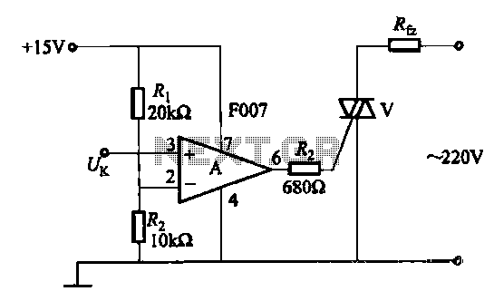
A transistor optocoupler interface circuit, as described in section 15.1.6, has been implemented. This circuit serves as a transistor interface with other circuits. The transistor optocoupler interface circuit utilizes a light-emitting diode (LED) and a phototransistor to achieve electrical isolation...
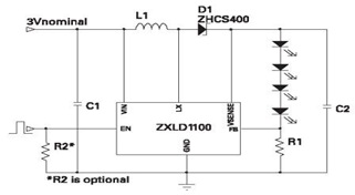
The ZXLD1100 is a PFM flyback DC to DC boost converter that operates in discontinuous mode. The following circuit diagram illustrates the configuration of four LED drivers for handset LCD backlighting using this device. The ZXLD1100 is designed to...

The following circuit illustrates a 20 dB VHF amplifier circuit diagram utilizing the BF197 transistor. Features include a simple circuit design. The 20 dB VHF amplifier circuit is designed to amplify very high frequency signals, making it suitable for applications...
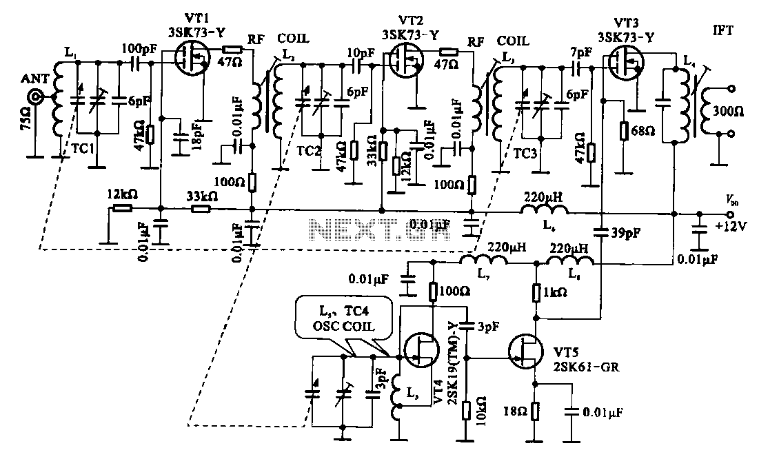
The FM radio circuit is represented by a double-gate MOS field-effect transistor. The high-frequency amplifier is a bipolar MOS field-effect transistor amplifier consisting of transistors VT1 and VT2. VT3 serves as the mixer. The local oscillator is formed by...
The following circuit illustrates a Dancing LEDs electronic circuit diagram. This circuit is based on the LM358 integrated circuit. Features: IC1A amplifies the signal. The Dancing LEDs circuit utilizes the LM358 operational amplifier to create a visually appealing light display....