
GSM Remote Control Temperature Control Schematic
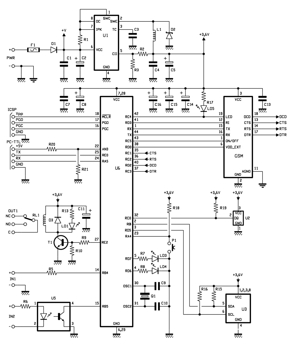
The microcontroller operates with an internal clock oscillator, although both the schematic and printed circuit board are designed to accommodate an external quartz crystal for potential future enhancements. After initializing the I/O lines, the microcontroller checks the logical state of the opto-isolated inputs related to line RB4, as well as lines RC4, RC5, RD0, RD3, and RX, which are essential for receiving notifications from the cellular module. Specifically, RD3 detects incoming calls by interfacing with the RI of the cellular module, while RC4 controls the GSM field LED by monitoring its output status. The microcontroller assesses radio coverage conditions based on the frequency and duration of impulses and adjusts accordingly. It features a UART that can be accessed via pins 44 (TX) and 1 (RX) for communication with the mobile device. The TX pin is used to periodically query the module for incoming SMS messages, while both TX and RX pins are engaged during calls and message exchanges with the GSM module. Control signals for the UART include CTS (Clear To Send), RTS (Request To Send), and DCD (Data Carrier Detect), which correspond to the signals from the cellular module. Lines RC5 and RD0 complete the I/O configuration for mobile communications, with RC5 managing the power state of the GSM (via a transistor on the mobile board) and RD0 handling mobile resets. The device's operational mode can be adjusted through a button connected to line RA3, which is configured as an input with an external pull-up resistor (R11), rendering it active at a low level. Notably, the management of inputs has been modified compared to the general scheme of the modular remote, allowing for direct reading of the room thermostat contact condition within the system.The full GSM thermostat is managed by a Microchip PIC18F46K20-I/PT microcontroller, programmed with a firmware that controls the temperature and takes care of the communication with the GSM module which is the component named GSM; this is, in fact the small board hosting the cell, so the pins` numbers refer to the used pin-strips` contacts. The fi rmware reads the room temperature by means of a smart probe Dallas DS1820, it controls the logical condition of the opto-isolated input and commands the relay when needed. Having said that, let`s now take a look at the electric scheme, starting by the power block, that from the input voltage (power applied to PWR, + and must be a continuous current at a value between 5 and 32 V) gets a stabilized component of 3.
6 V width by means of a switching regulator. The input voltage is filtered at the bottom by the diode protecting against polarity inversion (D1) through condensers C1 and C2. Fuse F1 enables you to protect both the circuit and the power source in case of short circuit in the integrated regulator discussed below.
The regulator is a U1 (a MC34063) and acts as a DC/DC converter step-down; it is used in the classic configuration of the series PWM regulators charged by inductance, whose output voltage depends on the energy stored in L1. The voltage it provides is stabilized providing feedback to the DC/DC through the demotion of a portion of the leveled component by condensers C4 and C5, made by the resistive divider R2/R3.
The 3. 6 volts present in these condensers are widely filtered by other condensers placed on the power lines of the microcontroller and of the GSM module; which presents, during transmission, absorption peaks compensated for by C7, C8, C13, C14, C15 and C16, thus avoiding than an impulsive current request may cause the microcontroller to be disturbed. The microcontroller is used in the configuration with an internal clock oscillator; both the scheme and the printed circuit are nevertheless equipped with external quartz, intended for future developments.
Once the I/O lines have been initialized, the microcontroller verifies the logical state of the opto-isolated inputs at voltage level related to line RB4 as well as that of lines RC4, RC5, RD0, RD3, RX, which are needed to receive the main notifications from the cellular module; more specifically, RD3 is used to detect incoming calls (it interfaces with the RI of the cellular module), while RC4 controls the GSM field LED , by reading the corresponding output status. The PIC understands the conditions of the radio coverage from the frequency and duration of the impulses, and then adjusts accordingly.
The microcontroller contains a UART accessible via pins 44 (transmission) and 1 (reception) which it uses to communicate with the mobile; more precisely, through the first pin (TX), it cyclically questions the module to check whether any SMS has been received, whereas both TX and RX are used for the communication between the microcontroller and the GSM module when making calls and receiving or sending messages. Regarding the UART, the following control signals are used: CTS (Clear To Send) RTS (Request To Send) and DCD (Data Carrier Detect), which correspond to those of the cellular module being used.
Lines RC5 and RD0 complete the set of I/Os destined to the mobile; the former controls the turning on and off of the GSM (through a transistor placed in the small board of the mobile), the latter takes care of resetting the mobile. The button for locally handling the operating mode of the device is read through line RA3, configured as input and equipped with an external pull-up resistor (R11), therefore active at a low level.
Special attention deserves the management of the inputs since here, compared to the general scheme of the modular remote, we find a variation: to directly read the condition of the room thermostat contact of the system where the circui 🔗 External reference
Related Circuits
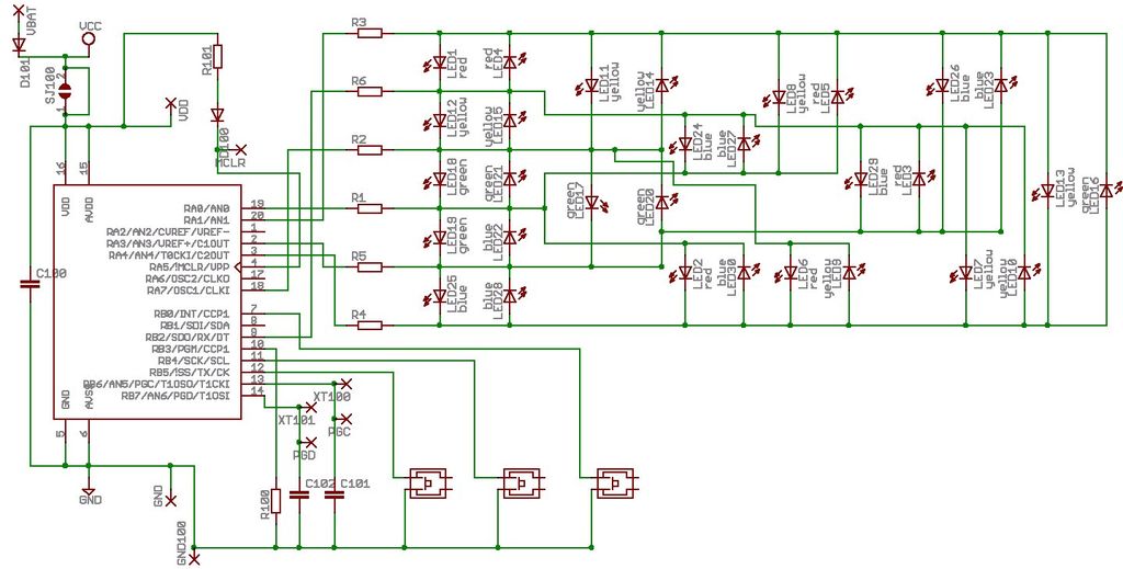
Microdot - wrist watch LED pattern timepiece. This project is a circuit board designed for creating a wristwatch-sized version. The Microdot wristwatch project involves the design and implementation of a compact circuit board that integrates LED technology to display time...
IR appliances use pulses (control signals) sent over a modulated IR carrier wave. The carrier wave may be modulated at various frequencies, 36-38KHz being the most popular. Some Satellite receivers use even higher frequencies than this. The IR1 remote...
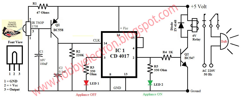
This circuit is a popular infrared (IR) remote control system designed for home appliances such as lamps, fans, radios, and TVs, allowing users to turn devices on or off using a TV, VCD, or DVD remote control. The design...
This shows the overall circuit diagram of the power control unit. On the left, there is a main relay controlled by the key switch. The power control unit circuit diagram illustrates the fundamental components and their interconnections, providing a clear...
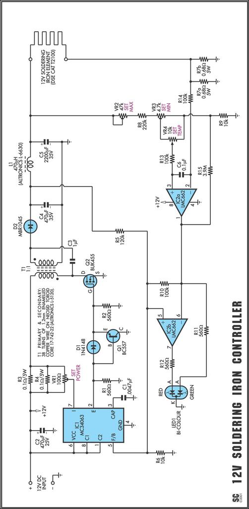
One reason commercial soldering stations are costly is that they typically use soldering irons equipped with built-in temperature sensors, like thermocouples. This circuit design eliminates the necessity for a specialized sensor by directly sensing the temperature of a soldering...
The TMP03 is a complete temperature data-acquisition system on a monolithic silicon chip. Including a silicon-based sensor, internal voltage reference, and sigma-delta A/D converter, it fits in a 3-pin (power, common, and output) TO-92 transistor package. Its digital output...
Warning: include(partials/cookie-banner.php): Failed to open stream: Permission denied in /var/www/html/nextgr/view-circuit.php on line 713
Warning: include(): Failed opening 'partials/cookie-banner.php' for inclusion (include_path='.:/usr/share/php') in /var/www/html/nextgr/view-circuit.php on line 713