
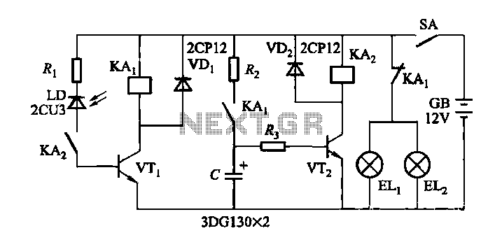
temperature controlled soldering iron

The described circuit operates by measuring the resistance of the soldering iron's heating element, which changes with temperature due to its positive temperature coefficient (PTC). The fundamental principle is that as the temperature of the heating element increases, its resistance also increases. This relationship allows the circuit to infer the temperature without relying on a separate temperature sensor.
The circuit typically includes a microcontroller or a dedicated analog circuit that can measure the resistance of the heating element. A voltage divider configuration can be employed, where the soldering iron's resistance is part of the divider. The output voltage from the divider will vary with changes in the resistance of the heating element, which can be read by the microcontroller's analog-to-digital converter (ADC).
To ensure accurate temperature readings, the circuit may incorporate calibration routines to establish a baseline resistance at a known temperature. This calibration process allows the system to create a lookup table or apply a mathematical formula to convert resistance readings into temperature values. Additionally, the circuit can include feedback mechanisms to adjust the power supplied to the heating element, maintaining the desired temperature by controlling the on/off state of the power supply.
Protection features, such as over-temperature cutoffs and thermal fuses, can also be integrated to prevent overheating and potential damage to the soldering iron or the circuit itself. Overall, this innovative approach not only reduces costs by eliminating the need for specialized sensors but also enhances the versatility of soldering stations, making them compatible with a wider range of soldering irons.One reason why commercial soldering stations are expensive is that, in general, they require the use of soldering irons with inbuilt temperature sensors, such as thermocouples. This circuit eliminates the need for a special sensor because it senses the temperature of a soldering iron heating element directly from its resistance.
Thus this circuit will, in principle, work with any iron with a resistance which varies predictably and in the right direction with temperature (ie, positive temperature coefficient).. 🔗 External reference
Related Circuits
When driving at night and approaching another vehicle, traffic regulations dictate that the distance between the two vehicles should be maintained. This is achieved by alternately activating and deactivating the high beams, while utilizing either the wide lights or...
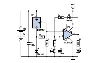
To determine whether it is freezing, it is necessary to measure the temperature accurately using a reliable temperature sensor. The LM35CZ, which operates between -40 to 110 °C, has been chosen for this purpose. This sensor generates an output...
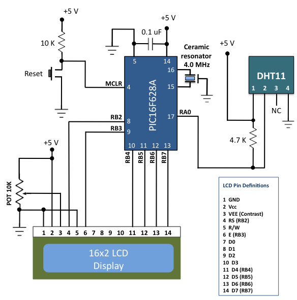
The DHT11 is the most affordable sensor currently available in the market that provides calibrated digital outputs for temperature and relative humidity. The DHT11 sensor is a low-cost digital sensor that measures both temperature and relative humidity. It operates...

A certain part of this circuit is directly connected to the AC mains; therefore, do not touch it while in operation. It is essential to exercise extreme caution when handling the AC mains supply during the construction of this...
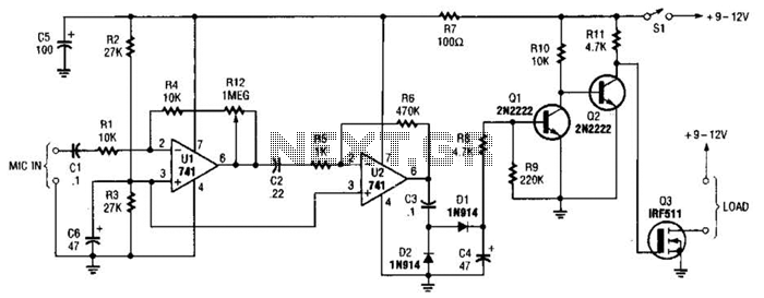
This audio-controlled switch integrates a pair of 741 operational amplifiers, two 2N2222 general-purpose transistors, an hcxFET, and several supporting components into a circuit capable of activating devices such as a tape recorder, a transmitter, or virtually any sound-activated equipment. The...
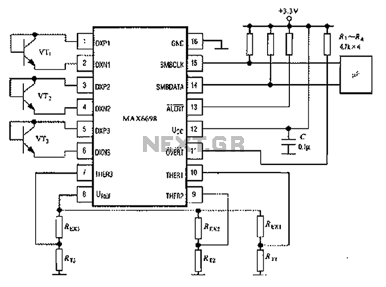
The circuit illustrated in the figure involves the MAX6698 maximum temperature sensor, which utilizes three transistors (VT1 to VT3) and three thermistors (RT1 to RT3). An internal reference voltage source is connected through resistors UREF REX1 to REX3, providing...