
ir remote control home appliance
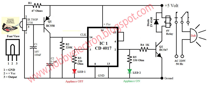
This infrared remote control circuit utilizes a basic yet effective design, suitable for controlling various household appliances. The heart of the system is the TSOP1738 IR receiver module, which effectively demodulates the incoming 38 kHz IR signals from standard remote controls. The connections to the TSOP1738 are critical: the ground connection ensures proper operation, while the resistor R5 limits the current to pin 2, preventing damage to the module.
The amplified signal from the BC558 transistor plays a vital role in driving the CD4017 decade counter. The CD4017 is a versatile IC capable of counting and driving outputs based on clock pulses. In this application, it serves to indicate the state of the appliance through the red and green LEDs. The red LED (LED1) signifies that the appliance is off, while the green LED (LED2) signals that the appliance is on. This visual feedback is essential for user interaction.
The relay (RL1) acts as the switch for the appliance, allowing it to be powered on or off based on the output from the CD4017. The inclusion of a freewheeling diode (IN4148) is crucial in protecting the circuit from voltage spikes generated when the relay coil is de-energized, thus ensuring longevity and reliability of the components.
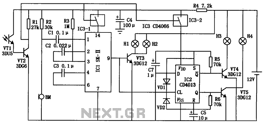
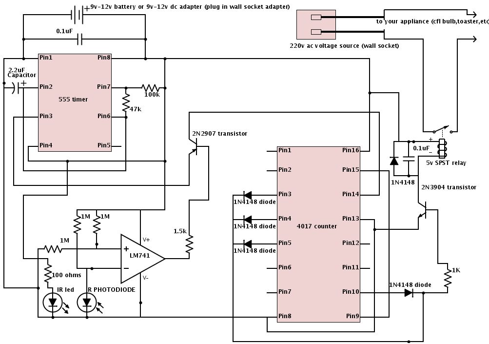
Adjusting the capacitance of C1 allows for fine-tuning of the circuit's response time. It is advisable to experiment with different capacitor values to achieve the desired delay and responsiveness. This flexibility in component selection and configuration makes the circuit adaptable for various applications, enhancing its utility in home automation projects.This is the most popular IR Remote control circuit for home appliances like lamp, fan, radio, tv etc to make the appliance turn on/off from a TV, VCD or DVD remote control. It is very simple to build because of few components and simple design. The circuit can activated from up to 10 metres. The 38kHz infrared (IR) rays generated by the remote con trol are received by IR receiver module TSOP1738 of the circuit. Pin 1 of TSOP1738 is connected to ground, pin 2 is connected to the power supply through resistor R5 and the output is taken from pin 3. The output signal is amplified by transistor T1 (BC558). The amplified signal is fed to clock pin 14 of decade counter IC CD4017 (IC1). Pin 8 of IC1 is grounded, pin 16 is connected to Vcc and pin 3 is connected to LED1 (red), which glows to indicate that the appliance is off.
` The output of IC1 is taken from its pin 2. LED2 (green) connected to pin 2 is used to indicate the on` state of the appliance. Transistor T2 (BC548) connected to pin 2 of IC1 drives relay RL1. Diode IN 4148 acts as a freewheeling diode. The appliance to be controlled is connected between the pole of the relay and neutral terminal of mains. It gets connected to live terminal of AC mains via normally opened (N/O) contact when the relay energises.
you can use any NPN transistor inplace of BC548. You can also use SL100 or any NPN transistor lying around you. The delay depends on the C1 capacitor. Using higher value capacitor will create more delay and using less value capacitor will switch the circuit more than 2 times when you press a remote. Analyse the circuit by placing the 10uf capacitor in place of C1 (100uf). 🔗 External reference
Related Circuits

The switching action of the 2N4990 enables the use of smaller capacitors while ensuring reliable triggering of thyristors. The 2N4990 is a high-speed switching transistor that plays a crucial role in applications requiring efficient control of thyristors. The device's rapid...
In certain industries, a computer-controlled 4-20 mA current loop is utilized to manage various equipment. This current loop is employed to transmit a signal over a distance. The 4-20 mA current loop is a standard method for transmitting analog signals...
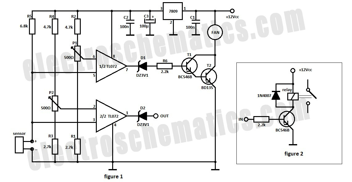
The automatic fan controller circuit depicted in the schematic features two comparators with distinct triggering points that can be adjusted independently. LM135 or... The automatic fan controller circuit is designed to regulate fan operation based on temperature variations. It employs...
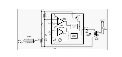
This circuit is designed around a 555 timer and utilizes a minimal number of components. Due to its simplicity, it can be easily constructed and operated by beginners. The circuit leverages the 555 timer IC, which is a versatile and...
The automatic electronic circuit depicted in the figure consists primarily of a voice circuit, an oscillation circuit, and a driving section for the display circuit. The automatic electronic circuit integrates several essential components to achieve its functionality. The voice circuit...
The schematic is provided below. It is recommended to construct it in three distinct sections, similar to the method demonstrated. The 555 timer circuit: connect pin 2 to pin... The schematic outlines a circuit design utilizing a 555 timer, a...