
Guitar Control
The circuit described involves two primary stages: an inverting amplifier stage and a tone control stage. The inverting amplifier, utilizing IC1A, operates by applying an input signal to the inverting terminal while the non-inverting terminal is grounded. The gain of this amplifier is adjustable through a three-way switch, which allows for the selection of different resistor values that are connected in parallel with R4. By changing the resistance, the overall feedback factor of the amplifier is altered, thus varying the gain according to the selected resistor.
In the subsequent tone control stage, IC1B is employed to implement a three-band equalizer. This stage is designed to modify the frequency response of the audio signal, allowing for adjustments in bass, midrange, and treble frequencies. The tone controls are typically configured as potentiometers that can boost or cut the selected frequency bands. At the center position of these controls, the circuit is designed to achieve a flat frequency response, ensuring that the output signal remains faithful to the input without any tonal coloration.
The integration of these two stages allows for a versatile audio processing circuit that can enhance sound quality according to user preferences. The inverting amplifier provides the necessary signal conditioning, while the tone control stage offers flexibility in adjusting the audio characteristics. Overall, this configuration is commonly used in audio applications where precise control over the sound output is desired.IC1A op-amp is wired as an inverting amplifier, having its gain set by a three ways switch inserting different value resistors in parallel to R4. This input stage is followed by an active three-band tone control stage having unity gain when controls are set in their center position and built around IC1B.
🔗 External reference
Related Circuits
This device is a long-standing controller for various home appliances, including night lights and air conditioners. It is a Miniature Real-time Controller that utilizes three primary components: an 89C2051 microcontroller, a DS275 or MAX232 level shifter, and a 74LS07...
This preamplifier was designed as a stand-alone portable unit, useful to control the signals generated by guitar pick-ups, particularly the contact "bug" types applied to acoustic instruments. Obviously it can be used with any type of instrument and pick-up....

Tutorials, reviews, and software regarding airsoft. This project illustrates how to connect a PC to a small FRS radio via a simple RS-232 interface. There are several reasons for this connection. This project focuses on establishing a communication link between...
The LM1036 is a DC controlled tone (bass/treble), volume and balance circuit for stereo applications in car radio, TV and audio systems. An additional control input allows loudness compensation to be simply effected. Four control inputs provide control of...
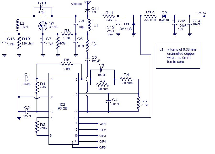
This article discusses a simple five-channel radio remote control circuit utilizing the TX-2B and RX-2B integrated circuits from Silan Semiconductors. The TX-2B/RX-2B is a remote encoder-decoder pair suitable for remote control applications. It features five channels, a wide operating...
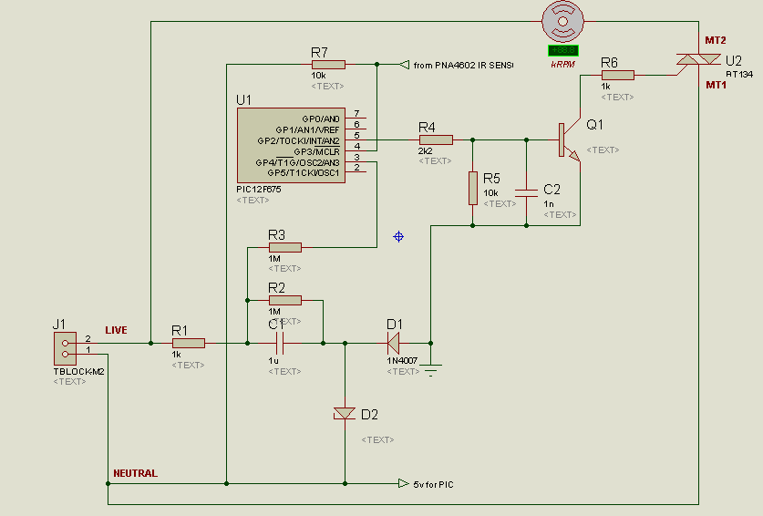
A project is underway to control the speed of an electric fan (220Vac, 60W, 5A max.) automatically using a microcontroller based on certain parameters. The circuit design for controlling the speed of an electric fan involves several key components to...
Warning: include(partials/cookie-banner.php): Failed to open stream: Permission denied in /var/www/html/nextgr/view-circuit.php on line 713
Warning: include(): Failed opening 'partials/cookie-banner.php' for inclusion (include_path='.:/usr/share/php') in /var/www/html/nextgr/view-circuit.php on line 713