
Guitar Tone Control

The described preamplifier circuit is a compact and efficient device tailored for enhancing the audio signals from various types of guitar pick-ups, with a particular emphasis on contact "bug" pick-ups commonly used in acoustic instruments. The unit's design prioritizes portability, making it suitable for musicians who require a lightweight and easily transportable solution.
The input section of the preamplifier includes a multi-position selector switch that allows the user to choose between three preset gain levels: -10dB, 0dB, and +10dB. This feature is crucial for adapting the circuit's sensitivity to different pick-up outputs, ensuring optimal signal integrity and preventing distortion. The ability to adjust gain levels makes the preamplifier versatile, accommodating a wide range of instruments and pick-up configurations.
In terms of power management, the preamplifier circuit is engineered for extremely low power consumption, operating at less than one microampere (µA). This characteristic not only contributes to the longevity of the battery life but also enhances the overall efficiency of the device, making it ideal for extended use during performances or practice sessions without the need for frequent battery replacements.
The circuit design likely incorporates operational amplifiers (op-amps) configured in a non-inverting amplifier setup, allowing for high input impedance and low output impedance, which is essential for interfacing with various pick-up types without loading them down. Additionally, the use of high-quality components and careful layout considerations can further reduce noise and improve signal fidelity.
Overall, this preamplifier serves as a practical solution for musicians seeking to enhance their instrument's sound while maintaining portability and efficiency. The thoughtful design elements, such as gain selection and low power consumption, make it a valuable tool for a wide range of acoustic applications.This preamplifier was designed as a stand-alone portable unit, useful to control the signals generated by guitar pick-ups, particularly the contact "bug" types applied to acoustic instruments. Obviously it can be used with any type of instrument and pick-up. It features a -10dB, 0dB and +10dB pre-set input selector to adjust input sensitivity, in order to cope with almost any pick-up type and model.
A very long battery life is ensured by the incredibly low current consumption of this circuit, i.e. less than µA. 🔗 External reference
Related Circuits
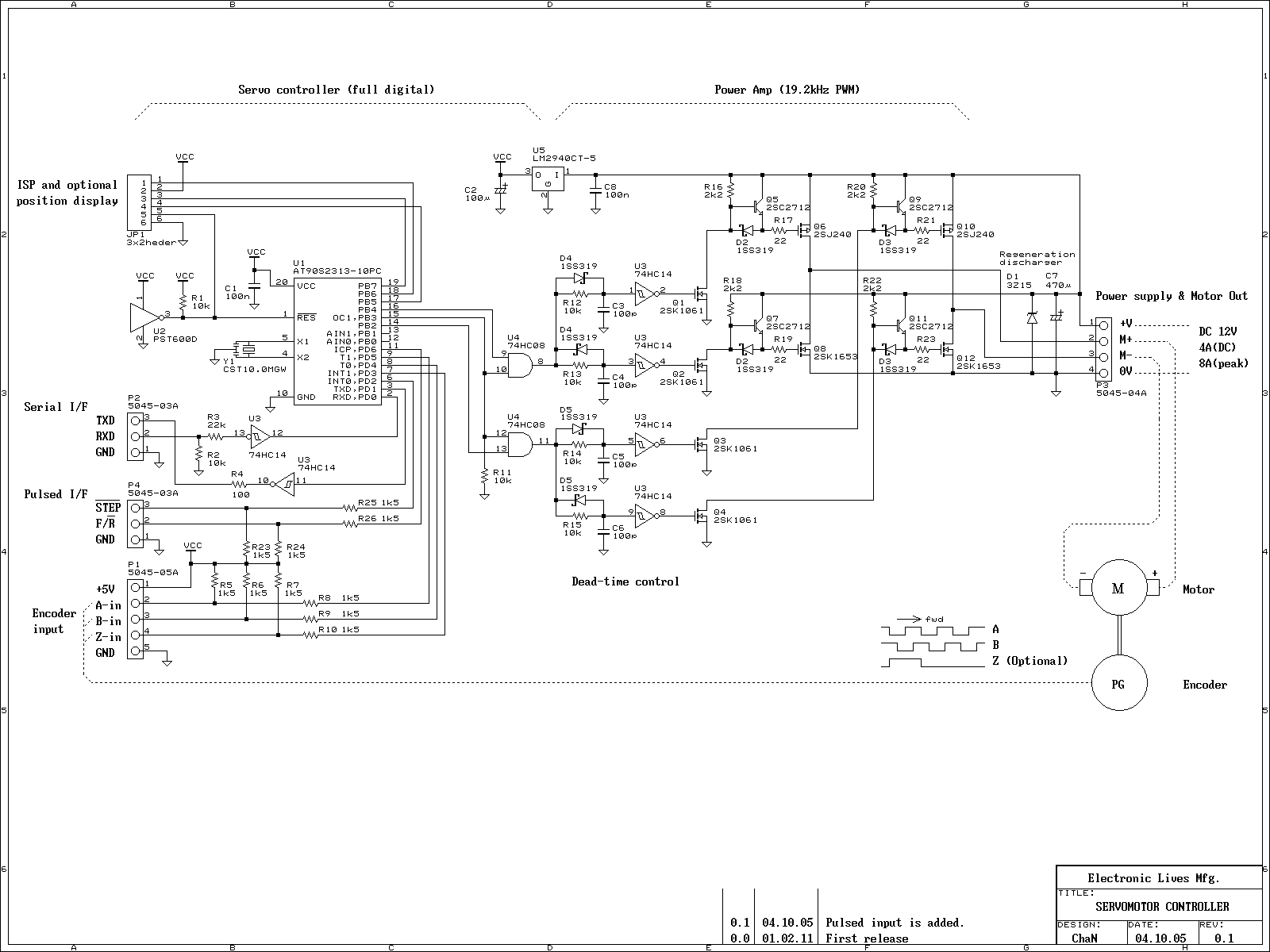
This is an experiment on the closed loop DC servomotor control system (SMC). It will be able to be used for practical use with/without some modifications. The closed loop servo mechanism requires real-time servo operations, such as position control,...
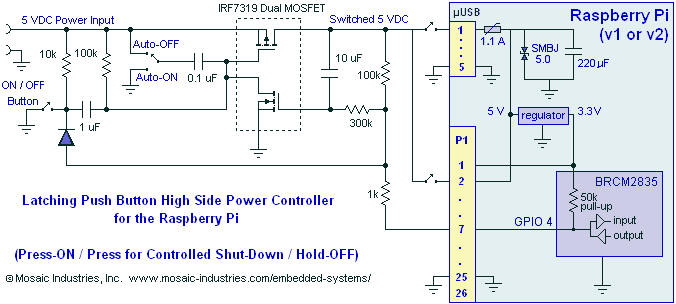
A momentary contact push button switch can be utilized to conveniently turn the Raspberry Pi (RPi) ON and OFF. Pressing the button will apply power to the micro USB header, maintaining power while the Raspberry Pi initializes and starts...
This article discusses the Gadgets, Gizmos, and Arduino (ATMega328). The content is straightforward and informative. The components mentioned in this article can enhance the understanding of the subject. For instance, readers can find and purchase components such as the...
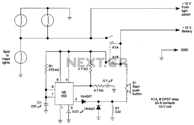
Pressing the START pushbutton activates either the headlights or spotlights for a specified duration. After 1 minute, determined by R1 and C1, the lights will turn off as the NE555 timer completes its cycle. The circuit utilizes a NE555 timer...
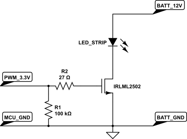
A strip of LEDs is controlled by a microcontroller using pulse-width modulation (PWM) to adjust brightness. The LED strip requires approximately 1.5A at 12V. The user, who has experience only with low-power digital electronics, seeks confirmation of their assumptions...
The T-40-16 and 555 ultrasonic transmitter circuit configuration consists of an ultrasonic transmitter T-40-16 and a 555 timer circuit. By adjusting the potentiometer RP, the oscillation frequency of the circuit can be changed. The output pulse frequency from the...