
Guitar Effect Bypass Circuit
The described circuit utilizes a 4011 NAND gate integrated circuit (IC) to create a debounced switch mechanism. This is essential in pedal applications where mechanical switches can produce noise and unintended multiple signals when engaged. The debouncing process ensures that only a single, clean pulse is sent to the next stage of the circuit, significantly improving reliability during operation.
Following the debouncing stage, the circuit employs a 4027 JK flip-flop configured in toggle mode. This flip-flop is pivotal for maintaining the on/off state of the effect pedal. When a pulse is received from the NAND gate, the flip-flop toggles its output state, effectively switching the pedal on or off. The JK flip-flop is advantageous in this application due to its ability to change states with each pulse, providing a straightforward means of control without additional complexity.
The overall design emphasizes a clean bypass, which is critical in audio applications to ensure that the signal remains unaffected when the effect is disengaged. The mechanical aspects of the circuit are also designed to minimize noise and ensure smooth operation, contributing to the overall performance of the effect pedals.
This circuit can be integrated into various effect pedal designs, allowing for consistent and reliable switching behavior. The combination of the 4011 NAND gate and the 4027 JK flip-flop provides a robust solution for electronic switching in musical applications, ensuring both functionality and quality in sound processing.Observing my "Boss" pedals and how they were switched on and off I figured there must be more to it. It took me only about 4 hours to design and test this circuit, It works very well and I`m really satisfied with it so I`ll be using it in all the effect pedals I build. It`s a very clean bypass both electronically and mechanically. How it works: the first stage in the schematic is a 4011 nand gate chip set up as a debounced switch to give the logic pulses from the switch to the flip flop. The second stage is the flip flop, this is a 4027 JK flip flop set up in toggle mode, this cont 🔗 External reference
Related Circuits
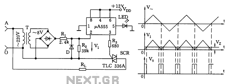
The zero volt switching circuit generates a trigger pulse at the zero crossing of the AC voltage. To facilitate this, the zero crossing of the 555 limit comparator is connected to a single form, with the comparison voltage set...
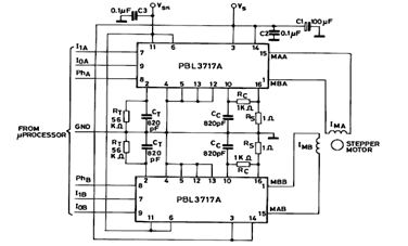
The diagram below illustrates a Two Phase Bipolar Stepper Motor Driver utilizing the PBL3717A. It depicts two PBL3717A integrated circuits (ICs) that control and drive two bipolar stepper motors. The Two Phase Bipolar Stepper Motor Driver circuit is designed to...
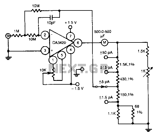
This circuit utilizes the exceptionally low input current of 0.1 pA from the CA3420 BiMOS operational amplifier. It employs a single 10-MΩ resistor. The circuit operates within a range of ±50 pA, achieving a maximum full-scale sensitivity of ±1.5...
The circuit is a battery charging system powered by Q2, Q6, R8, and D10, which provides constant current to charge the battery. When an external power supply is present, the charging current flows through R8 and D10 to charge...
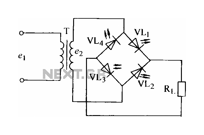
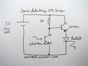
In certain applications, the current from a non-rectified voltage power supply circuit is insufficient. A light-emitting diode (LED) rectifier circuit can be employed to address this issue, serving as a power indicator. It is important to ensure that the...
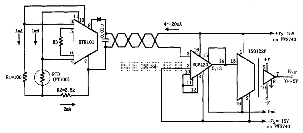
The circuit comprises an isolated RTD loop current configuration utilizing the XTR101 for transmitting loop current and the RCV420 for receiving it. The instrumentation amplifier detects changes in temperature via a resistance temperature detector (RTD), converting these changes into...
Warning: include(partials/cookie-banner.php): Failed to open stream: Permission denied in /var/www/html/nextgr/view-circuit.php on line 713
Warning: include(): Failed opening 'partials/cookie-banner.php' for inclusion (include_path='.:/usr/share/php') in /var/www/html/nextgr/view-circuit.php on line 713