
Noise-producing sound effects using NE555
The circuit consists of two primary components: the tone generator (U2) and the modulation source (U1). The 555 timer IC (U2) is configured in astable mode, allowing it to produce a continuous square wave output. The frequency of this output can be modified by adjusting the resistance value of the potentiometer R5, which is connected in the timing network of the 555 timer. This enables the user to select different tones that will be transmitted through the speaker.
The modulation of the tone is achieved by the second 555 timer IC (U1), which is also configured in astable mode to generate a sawtooth waveform. This waveform serves as the modulation signal for the output of U2. The frequency of the sawtooth waveform can be adjusted using potentiometer R4, allowing for control over the modulation rate. The interaction between the tone generated by U2 and the modulation from U1 results in a complex audio output that varies in pitch and amplitude, creating the desired noisy atmosphere.
The circuit's design allows for flexibility in sound generation, making it suitable for applications such as sound effects in electronic devices or artistic audio installations. The use of discrete components, such as resistors and capacitors, in conjunction with the 555 timer ICs, provides reliability and ease of assembly. The schematic would illustrate the connections between the two 555 timers, the potentiometers, and the speaker, demonstrating how the modulation and tone generation work together to create the final audio output.Tools that created this is to produce noisy atmosphere. This circuit is quite simple, this circuit controlled by two 555 timer IC is assisted by other discrete component resistors and capacitors. The first 555 timer U2 will generate a tone which can be heard on the frequency can be set using a potentiometer R5.
next U2 output is given directly to the speaker or speakers. But in this case the speaker will not produce a constant tone. This is because the U2 is modulated by the sawtooth waveform generated by U1. The following is a schematic drawing: Sawtooth frequency that can be set using the potentiometer R4. The end result will be obtained modulated signal high and low tones that can be arranged with R5 while the modulation rate set by R4. 🔗 External reference
Related Circuits
This circuit demonstrates the application of a 4017 CMOS decade counter to construct a timer circuit. The push-button switch S1 discharges capacitor C1 through resistor R2. Upon releasing S1, capacitor C1 charges through resistor R1, generating a rising edge...
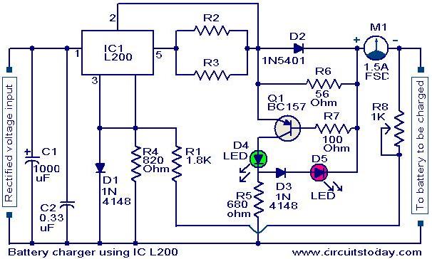
A simple battery charger circuit with reverse polarity indication is presented here. The circuit utilizes the L200 integrated circuit (IC), which is a five-pin variable voltage regulator. The charging circuit can be powered by DC voltage from either a...
This instructable is categorized under 13 - 18 in the National Robotics Week Robot Contest. The National Robotics Week Robot Contest encourages innovation and creativity in robotics among participants aged 13 to 18. This category represents a significant opportunity for...
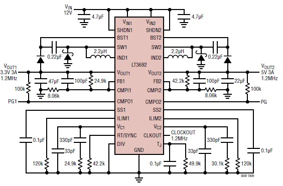
A 3.3V and 5V DC-DC converter circuit design project utilizing the LT3692 dual tracking regulator. The LT3692 is a highly efficient dual-output DC-DC converter designed for applications requiring both 3.3V and 5V outputs. This integrated circuit can provide a regulated...
This article describes a 2-Input alarm developed on the PIC LICK-1 Module using a Microchip PIC16F628-04. The program uses the internal 4MHz oscillator and if any other frequency is used, the timer values will need to be changed. A...
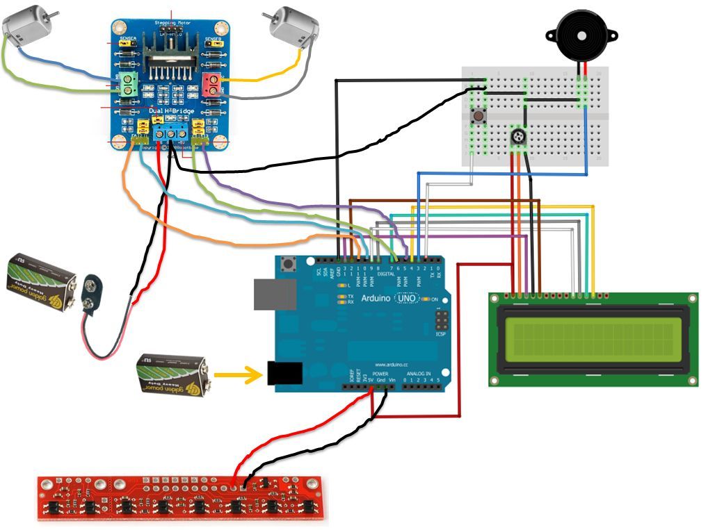
If the robot is positioned on the black line, it will continue moving forward. However, if it veers off the line and enters a white area, it will assess whether to correct its path to the left or right,...
Warning: include(partials/cookie-banner.php): Failed to open stream: Permission denied in /var/www/html/nextgr/view-circuit.php on line 713
Warning: include(): Failed opening 'partials/cookie-banner.php' for inclusion (include_path='.:/usr/share/php') in /var/www/html/nextgr/view-circuit.php on line 713