
Guitar Titan Boost and Titan Octave effects


The described boost circuit is designed to elevate a 9-volt battery supply to an output voltage of 30 volts peak-to-peak (pk/pk). This type of circuit is often used in applications where higher voltage levels are necessary, such as in audio processing or signal modulation. The core component of the circuit is a boost converter, which utilizes an inductor, a switch (typically a transistor), a diode, and a capacitor to step up the voltage.
The operation of the boost converter begins when the switch is closed, allowing current to flow through the inductor, which stores energy in the form of a magnetic field. When the switch opens, the inductor's magnetic field collapses, inducing a voltage across the inductor that adds to the input voltage, thus generating a higher output voltage. The output voltage can be regulated by adjusting the duty cycle of the switch.
In this specific design, the integration of a germanium (Ge) diode bridge enhances the functionality of the circuit. The Ge diodes are known for their low forward voltage drop, which minimizes power loss and improves efficiency. The diode bridge converts the output of the boost converter from alternating current (AC) to direct current (DC), which is suitable for various electronic applications.
The circuit can be further optimized by including filtering capacitors at the output to smooth the voltage and reduce ripple, ensuring a stable output for sensitive applications. Additionally, feedback mechanisms can be implemented to stabilize the output voltage against variations in load or input voltage.
This boost circuit configuration, combined with the Ge diode bridge, creates a robust solution for generating higher voltage outputs from a lower voltage source, making it particularly useful in audio applications such as octave boxes, where the manipulation of sound signals is required.A simple boost circuit that gives 30 volts pk/pk output using a 9 volt battery. The addition of a Ge diode bridge makes a surprisingly good octave box. 🔗 External reference
Related Circuits
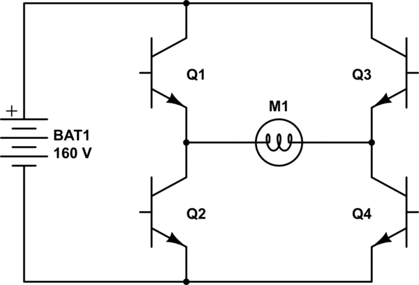
The project involves controlling a single-phase AC induction motor using two IGBTs. One IGBT is designated for switching the PWM signal to the motor, with a fixed PWM frequency of 16 kHz, while the second IGBT is employed for...
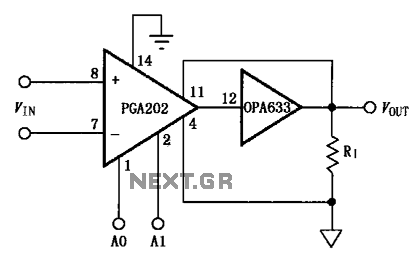
The figure illustrates a current boosting circuit configuration utilizing the PGA202 and OPA633 operational amplifiers. This circuit enhances the output current capability of the PGA202 operational amplifier, leveraging the performance characteristics of the OPA633 to achieve a higher output...
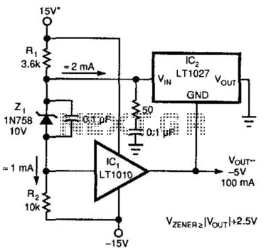
A method for enhancing the output current of a reference while also providing overload protection is illustrated. In this configuration, IC1 functions as a power buffer. The LT1027 regulates the output voltage (Vout) and ground to maintain a stable...
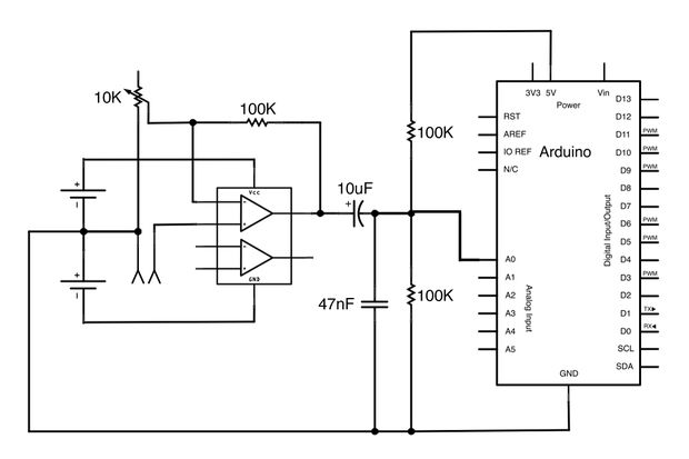
This Arduino-powered vocal effects box pitch shifts and distorts incoming audio signals to produce a wide variety of vocal effects. This project serves as an experiment with real-time digital signal processing using Arduino. It samples an incoming microphone signal...
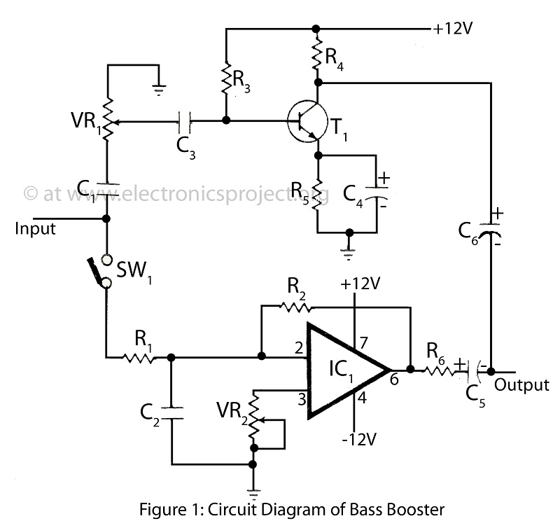
The bass booster featured on this website enhances the beat frequency while maintaining the integrity of the high-frequency response. The circuit diagram for the bass booster, along with various radio circuits, is also provided. The bass booster circuit operates by...
This design is based on an 18 Watt Audio Amplifier and was developed primarily to address the needs of users who have difficulty locating the TLE2141C chip. It utilizes the commonly available NE5532 Dual IC; however, its power output...