
speedcontroller Dead time effects Of IGBTs
The control of a single-phase AC induction motor utilizing two Insulated Gate Bipolar Transistors (IGBTs) is a common approach in power electronics. The first IGBT is responsible for modulating the power delivered to the motor through Pulse Width Modulation (PWM) at a fixed frequency of 16 kHz. This frequency is selected to optimize the motor's performance while minimizing audible noise and losses associated with switching.
The second IGBT serves a crucial role in the freewheeling path, allowing for the dissipation of energy stored in the motor's inductance when the PWM signal is turned off. This is essential for preventing voltage spikes that could damage the IGBT or other circuit components and ensures smooth operation of the motor.
The dead time inherent in IGBT switching introduces a delay between the turn-off of one IGBT and the turn-on of the other. This delay can lead to several issues, including increased switching losses, reduced efficiency, and potential motor stalling or jitter. The effects of dead time can be quantified in terms of increased harmonic distortion in the motor current and voltage, which may lead to overheating and reduced lifespan of the motor.
To mitigate the adverse effects of dead time, several strategies can be employed. In hardware design, utilizing gate drivers with adjustable dead time settings can optimize the switching characteristics for the specific application. Additionally, incorporating snubber circuits can help absorb voltage spikes and dampen oscillations caused by switching transients.
On the software side, implementing advanced control algorithms, such as field-oriented control (FOC) or direct torque control (DTC), can enhance the motor's responsiveness and efficiency. These algorithms can be designed to compensate for the dead time by predicting the next switching state based on the current operating conditions, thus reducing the impact of delays on motor performance.
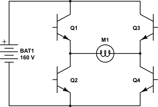
In conclusion, careful consideration of IGBT dead time is essential in the design of a PWM-controlled single-phase AC induction motor system. By employing both hardware and software remedies, it is possible to minimize the negative effects of dead time, ensuring reliable and efficient motor operation.Project to control single phase ac induction motor in which I planned to use two IGBTs, one for switching the PWM to the motor (for AC chopping, PWM frequency is fixed @16khz) and one for freewheeling the motor. A symbolic circuit is included here: I know the dead time of IGBTs is going to have some effect on the system.
I want to know how worst the system is going to be effected because of this dead time and what are the remedies with respect to hardware and software. 🔗 External reference
Related Circuits
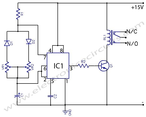
The two circuits demonstrate the use of a 555 timer to activate a relay for a specified duration when a momentary normally open (N/O) push button is pressed. The circuit on the left is designed for extended time periods,...
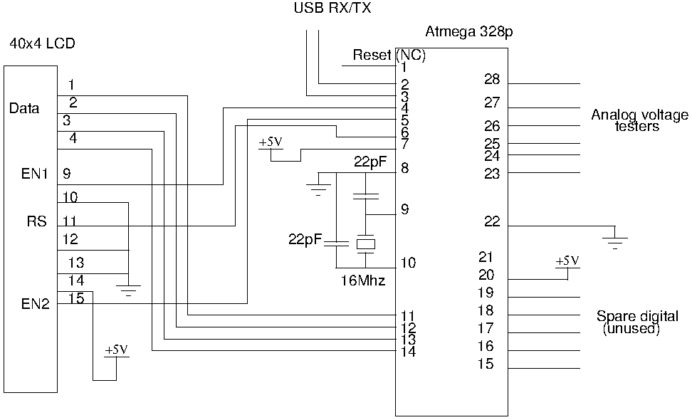
Drive a four-line LCD panel using an Arduino. The project initially aimed to control the LCD for displaying arbitrary information but evolved to include functionalities such as timekeeping, EEPROM read/write operations from the Atmel 328p, and voltage measurement. Multiple...
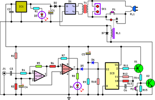
This circuit deactivates an amplifier or any connected device when a low-level audio signal at its input is absent for at least 15 minutes. Pressing P1 turns the device on, supplying power to any appliance connected to SK1. The...
555 Timer with On-Off Delay Circuit. This circuit utilizes the commonly available 555 integrated circuit (IC) to create a timer that allows for time adjustment in both on and off states. The 555 timer is a versatile device widely used...
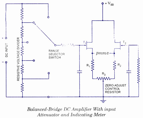
The electronic multimeter is a versatile general-purpose instrument capable of measuring both DC and AC voltages, as well as current and resistance. This solid-state device typically includes a built-in power supply for operation on AC mains and often features...
This project is suitable for individuals who enjoy experimenting with electronics. It presents a low risk of damaging the unit. This project involves creating a simple electronic circuit that allows users to engage in hands-on experimentation without significant risk. The...