
h-bridge basics

The H-bridge circuit is a vital component in motor control applications, allowing for the bidirectional control of brushed DC motors. It consists of four switches arranged in a bridge configuration. The switches, typically implemented using transistors, enable the reversal of current direction through the motor, thereby controlling its rotation direction. The catch diodes serve to protect the circuit from back EMF generated by the motor during operation, ensuring that any induced voltage does not damage the switching elements.
In practical applications, the H-bridge can be controlled using PWM (Pulse Width Modulation) techniques to regulate motor speed. By adjusting the duty cycle of the PWM signal applied to the gates of the transistors, the effective voltage across the motor can be varied, allowing for fine control over the motor speed. Additionally, feedback mechanisms, such as encoders or current sensors, can be integrated into the system to enhance control accuracy and performance.
It is essential to implement proper thermal management strategies when designing H-bridges, as the switching elements can generate significant heat during operation. Adequate heat sinking and thermal monitoring can help maintain optimal operating conditions, preventing thermal runaway and ensuring longevity of the components.
Overall, the H-bridge circuit is a fundamental building block in modern motor control systems, enabling efficient and flexible operation of various types of electric motors across a wide range of applications. Understanding its operation and design considerations is crucial for engineers and designers working in the field of electronics and motor control.Learn how to build h-bridges from many on- and off-line resources. After all these circuits are not terribly complicated. Some of those resources are good, some are not so much. However when I`ve started working with them, I`ve realized that many of my experiences were not documented and some of the things I`ve learned seemed to be missing from those descriptions. So I decided to write down what I`ve learned and try to organize that description into an easy to understand yet comprehensive structure. This work started off as a three-part series I`ve written, while developing the µModule H-bridge. While the current material is based on those articles, it corrects many errors and is expanded and updated greatly.
My intention is to cover more ground than most articles I`ve seen on the subject. While I don`t expect the you, dear reader, to be familiar with h-bridges or motors controllers in general, I do build upon basic electrical circuit understanding. So if you don`t know what a resistor, an inductor or a capacitor is, if you don`t understand at least the basics of time- and frequency-domain circuit analysis, you`re not reading the right article.
You probably won`t be able to follow the discussion. But if you`re interested in motor control background information, if you want to understand the reasons behind design decisions, if you want to gain deeper knowledge not just in the h-bridges, but in what goes on before and after them, you have found your place. The switching elements (Q1. Q4) are usually bi-polar or FET transistors, in some high-voltage applications IGBTs. Integrated solutions also exist but whether the switching elements are integrated with their control circuits or not is not relevant for the most part for this discussion.
The diodes (D1. D4) are called catch diodes and are usually of a Schottky type. Though the load can in theory be anything you want, by far the most pervasive application if H-bridges is with a brushed DC or bipolar stepper motor (steppers need two H-bridges per motor) load. In the following I will concentrate on applications as a brushed DC motor driver. The basic operating mode of an H-bridge is fairly simple: if Q1 and Q4 are turned on, the left lead of the motor will be connected to the power supply, while the right lead is connected to ground.
Current starts flowing through the motor which energizes the motor in (let`s say) the forward direction and the motor shaft starts spinning. In a bridge, you should never ever close both Q1 and Q2 (or Q3 and Q4) at the same time. If you did that, you just have created a really low-resistance path between power and GND, effectively short-circuiting your power supply.
This condition is called shoot-through` and is an almost guaranteed way to quickly destroy your bridge, or something else in your circuit. While modeling DC motors is a complicated topic, one that you can read on extensively here, for this article, let`s just start with a very simple model!
This model will not be useable for control applications, where you try to electrically compensate for the effects of mechanical components. The main assumption in the model introduced here is that the mechanical time-constants in your system are much higher than the electrical ones, in other words we can consider the shaft speed to be constant for our analysis.
That`s true in almost all cases, but you`ll need to read other articles to understand why. For now, you`ll have to take my word for it. A DC motor is an energy conversion device: it takes electrical energy and turns it into mechanical energy. When operated as a generator, it does the opposite: converts mechanical energy into electrical. In this very simple motor model, the mechanical parameters are completely ignored. On the electrical side, the motor basically contains a number of inductors, that move in a magnetic field.
The inductors themselves of course have an inductance, 🔗 External reference
Related Circuits
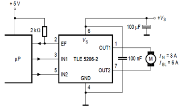
The schematic below illustrates the TLE5206-2 5A H-Bridge circuit for DC motor applications. This device features an integrated power H-bridge with DMOS output stages designed specifically for driving DC motors, as indicated in the datasheet. The TLE5206-2 circuit application...
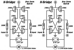
This diagram illustrates the 6-transistor Tilden H-bridge circuit. While it is not as old as the original basic H-bridge, it has a significant history and serves as the foundation for many BEAM driver circuits. Revised drawings were created for...
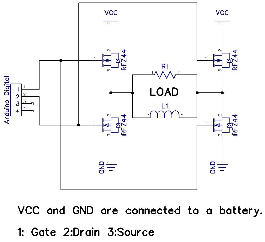
The H-Bridge is a circuit that can drive a motor in both forward and reverse directions. It can be a straightforward circuit that requires only a few components. The H-Bridge circuit is a fundamental configuration used in motor control applications,...
I decided to make a commercial surface mount PC board using the LED2 sensor concept. It is quite sensitive and can track to a few degrees of accuracy in bright sunlight. If a blocking shadow is used the accuracy...
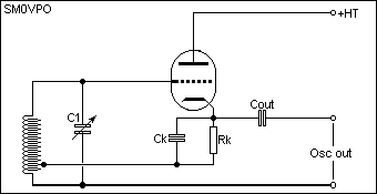
Observing the bottom of a valve reveals the wires connected to each electrode and the valve base pins. Therefore, specific valve data or pin-outs will not be provided, as this information is widely accessible from various sources, and most...
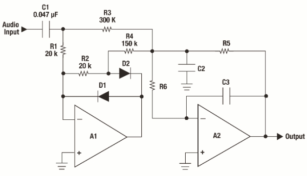
Audio metering is prevalent in various devices that play or record audio, ranging from cell phones displaying bar graphs of audio output levels to home stereos with flashing LEDs and live broadcasting equipment. Multiple standards exist for audio metering,...