
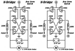
6 Transistor Tildens H-Bridge
The following diagram represents a 16W audio amplifier circuit built using two LM383 power ICs in a bridge configuration, classifying it as a bridge amplifier. The LM383 is discontinued, making it challenging to source; alternatives include ECG1232, TDA2002, or TDA2003. The parts list includes: R1, R2, R4, R5 = 270Ω; R3 = 2.7Ω; VR1 = 10KΩ logarithmic potentiometer; TR1 = 470KΩ trimmer; IC1, IC2 = LM388; C1 = 100µF/25V; C2 = 100nF; C3 = 10µF/25V; C4, C5 = 22µF/25V; C6 = 47nF.
Additionally, a 4W bridge amplifier circuit design based on the LM388 power IC is presented, featuring two chips. This circuit diagram depicts an amplifier with four input channels and four output channels, commonly referred to as a quad amplifier. It is specifically designed for car audio systems, providing significant output power per channel, low distortion, and low output noise, making it suitable for simple car amplifiers.
A simple bridge amplifier circuit based on the TDA7240A is also included, intended for car audio systems but adaptable for small home audio applications. The TDA7240A is a 20W bridge audio amplifier IC designed specifically for car radio applications, requiring few external components.
The circuit diagram of the Vox Tone Bender Pedal is similar to that of the Fuzz Face pedal, offering more treble response to enhance the sound of typically "dark" British amplifiers.
Lastly, a circuit consisting of an infrared transmitter-receiver pair utilizes IR beam transmission to control a toy car, enabling it to switch on or off. Modifications can be made to allow the toy car to turn left or right.
The comprehensive nature of these designs highlights their versatility and application in various audio and control systems. Each circuit serves a unique function, from amplifying audio signals to controlling devices wirelessly. The included parts lists ensure that builders can source the necessary components for successful implementation, while the detailed descriptions of each circuit provide insights into their operational principles and intended uses.This diagram is certainly the 6 transistor Tilden H-bridge circuit; while not as old as the original basic H-bridge, this goes way back, and will be the basis for a lot of BEAM driver circuits. I did a few revised drawings for Ian quite a while back, so he could place them up at beam-online. However, they did not get posted inside the midst of the a lot of revisions he was doing. Attached (begging Ian`s indulgence), will be the two versions of the circuit, one which turns on having a Positive input, the other (for quadcores) having a Negative input. Ian shows 100k input resistors. I`ve been applying 47k resistors with success. Tilden`s report recommends nothing lower than 50k (I assumed 47k was near enough) and up to 20 Meg or so.
The following diagram is 16W audio amplifier circuit. The circuit built based 2 pieces of power IC LM383 in bridge connection, so this amplifier is an bridge amplifier. This is an old amplifier, LM383 is discontinued, so this LM383 might be difficult to find. You can use ECG1232, TDA2002 or TDA2003 as the replace for. Parts List: R1-2-4-5=270 © R3 = 2. 7 © VR1 = 10K © Log. Pot. TR1 = 470K © Trimmer IC1-2 = LM388 C1 = 100uF/25V C2 = 100nF C3 = 10uF/25V C4-5 = 22uF/25V C6 = 47nF This is the 4W bridge amplifier circuit design based on power IC LM388 as the main component.
Currently there are 2 chips. Here`s a circuit diagram of an amplifier that has four input channels and four output channels or commonly called the quad amplifier. Power amplifier is designed specifically for car audio system applications. With a fairly large output power per channel, low distortion and low output noise features; amplifier is suitable for your car simple amplifier.
This is a simple bridge amplifier based on TDA7240A. This circuit is designed for car audio system, but you may use this circuit for your small home audio application. :) Schematic Diagram: PCB Layout: About TDA7240A: The TDA7240A is a 20W bridge audio amplifier IC designed specially for car radio applications.
The low external component. This is the circuit diagram of Vox Tone Bender Pedal. The circuit is very similar to Fuzz Face pedal. The Vox ToneBender will have a lot more treble response than the Fuzz Face. maybe to help brighten up those characteristically "dark" sounding British amps some. Using a Vox ToneBender with a Fender Twin, or any other. The circuit, consisting of an infrared transmitter-receiver pair, utilizes IR beam transmission to switch the toy car on` or off`, yeah. it will be only switching on and switching off, you may modify this circuit to make the toy car to turn left or right.
To operate the toy car, you have to hold the. 🔗 External reference
Related Circuits
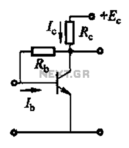
Basic reference bias circuit using a transistor with negative voltage feedback. The basic reference bias circuit utilizing a transistor with negative voltage feedback is designed to provide a stable output voltage or current that is largely independent of variations in...
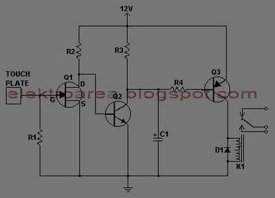
This document describes a series of touch switches that utilize only three transistors. These touch-based transistor switches can activate a load simply by the user touching a metal plate. They are designed to directly switch a relay, enabling operation...
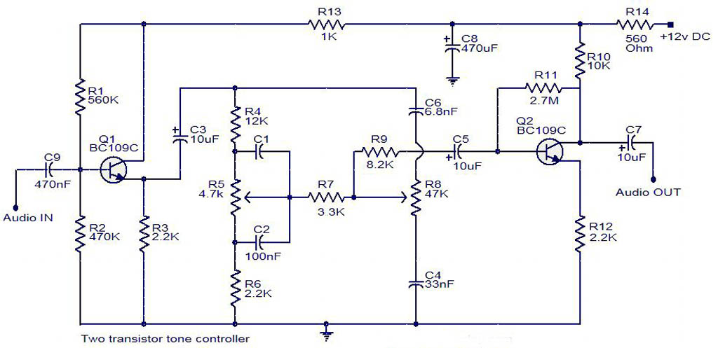
The electrical schematic diagram presented below illustrates a simple two-transistor tone controller audio circuit, which is available for free download. This circuit is based on the well-known Baxandall tone control design. Variations in the values of the transistor components...
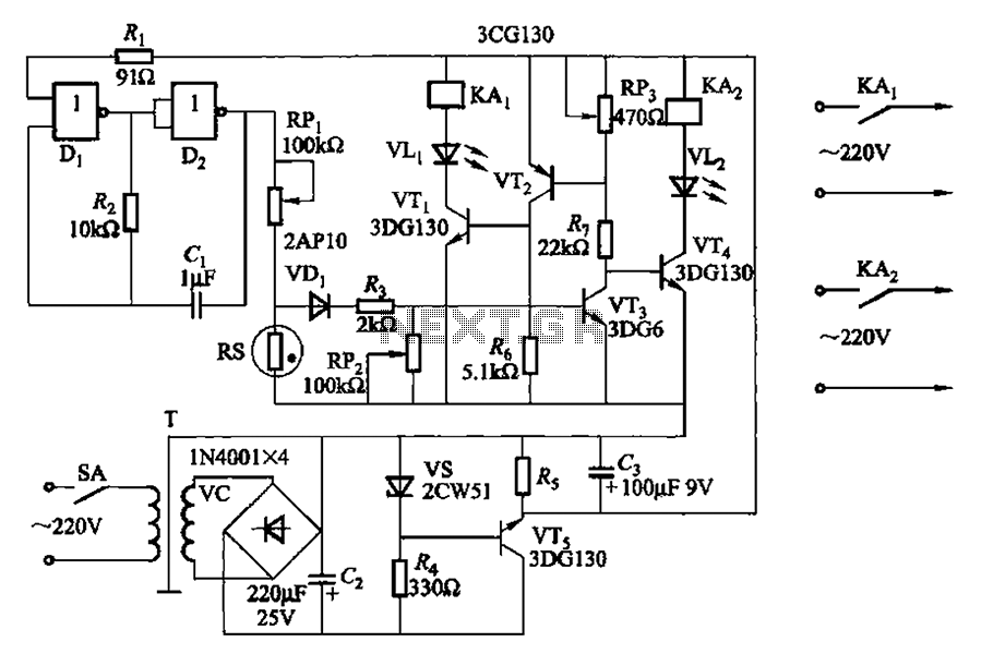
Two NAND gates (Di, Dz) and a resistor (Rz) along with capacitors (C1, etc.) form an RC self-excited multivibrator with an oscillation frequency of 2.5 Hz and an oscillation amplitude of 4 V. This circuit is used as a...
This is basically a high gain amplifier with feedback that causes the LED to flash at a rate determined by the 10u and 330k resistor. Remove one of the transistors and insert the unknown transistor. When it is NPN...
The following circuit illustrates a Power Amplifier Circuit Diagram utilizing a 2N3055 transistor. Features include a 500-ohm current and an optimal voltage of 50V. The power amplifier circuit based on the 2N3055 transistor is designed to deliver significant output power,...
Warning: include(partials/cookie-banner.php): Failed to open stream: Permission denied in /var/www/html/nextgr/view-circuit.php on line 713
Warning: include(): Failed opening 'partials/cookie-banner.php' for inclusion (include_path='.:/usr/share/php') in /var/www/html/nextgr/view-circuit.php on line 713