
H-bridge

In designing a general-purpose H-bridge circuit board, a jumper was included for each bridge. When no pins are connected, the brake is disabled. When adjacent pins are connected, the brake is activated by either a (0, 0) or a (1, 1) input, depending on the jumper configuration. For specific applications, it is not necessary to provide an actual jumper block. For the bridge input resistors, a 47k fixed resistor is included to prevent overstaturation in case a trimpot is turned down too far, along with a 100 k trimpot for fine adjustment and a 1.0 M trimpot for coarse adjustment. Preferred components are 6 mm Panasonic trimpots, available from Digikey. It was noted that tuning a motor with a ten-turn pot was cumbersome, and the Panasonic trimpots have a lifespan of 50 turns, making them unsuitable for circuits requiring constant adjustment. Alternatives include using fixed value resistors or a through-hole fixed resistor for coarse adjustment paired with a 100k trimpot for fine tuning, which may be beneficial for a two-motor rolling robot.
After working with the first prototype H-bridge board, it became evident that having the two enable lines from the 74HC139 chip accessible off the board was useful, though it complicated development work due to the need to remember to connect the enable lines to ground. Consequently, a pair of 100 k pulldown resistors were soldered to the bottom of the board, allowing the two halves of the chip to be permanently enabled while still permitting direct enable/disable signals. Optimization of the transistors for each application was deemed unnecessary; instead, PN2907 and PN2222 transistors were selected for motor control, providing a comfortable 1/2 amp capability and supporting up to 800 mA if required. The 2N3904 and 2N3906 transistors are also usable, handling 100 mA comfortably, while 2N3906 transistors are employed to control other transistors due to their lower current handling. Despite the prevalence of H-bridge designs lacking anti-noise capacitors, this simple fix has resolved erratic behavior in numerous robots. The chosen approach for actual circuits involves using through-hole components on home-etched circuit boards, with the second prototype featuring 135 holes for component placement.
The overall design of this H-bridge circuit emphasizes flexibility and ease of use while maintaining effective braking and motor control capabilities. The integration of adjustable resistors allows for fine-tuning of motor operations, and the inclusion of pulldown resistors enhances stability during development. The choice of robust transistors ensures reliable performance across a range of current requirements, making this circuit suitable for various robotic applications.I had always assumed that dynamic braking would be most effective at higher speeds. However, actual tests using a Faulhaber (micro mo) gear motor showed that the brake would hold a motor almost stationary. These gearmotors are so well made that I can turn the 4 mm diameter shaft with light finger pressure.
For the tests I had mounted a 90 mm diameter wheel, which gave me tremendous mechanical advantage. I found with the wheel mounted that I could barely turn the motor against the brake. When I spoke to Wilf Rigter about this feature, he suggested that the brake would be very power hungry as originally designed. He guessed it would draw around 50 to 100 mA which I confirmed by actual measurement. At Wilf`s suggestion I added a resistor next to each diode in the brake. He recommended resistors in the range 1000 to 5000 ohms; I found 1000 ohm resistors give almost instant braking with only 5 mA current draw.
When I designed my general purpose H-bridge circuit board, I provided a jumper for each bridge. With no pins connected, the brake is disabled. With a pair of adjacent pins connected, the brake is applied by either a (0, 0) input, or a (1, 1) input, depending which way the jumper is connected. Of course, for a specific application it isn`t necessary to provide an actual jumper block. For the bridge input resistors, I show a 47k fixed resistor (to prevent overstaturation in case a trimpot gets turned down too far), a 100 k trimpot for fine adjustment, and a 1.
0 M trimpot for coarse adjustment. The pots I like to use are 6 mm Panasonics, sold by Digikey (about $. 50 US each). I found trying to fine tune a motor with a ten turn pot was a pain. Note that the Panasonic trimpots have a life of 50 turns, so they should not be used in a test-rig circuit that you will be constantly adjusting. There are plenty of alternatives. One is to simply use fixed value resistors and not worry about balancing motor speeds at the bridge. For a walker this seems to be the best approach. Another idea is to use a through-hole fixed value resistor for coarse adjustment, and a 100k trim pot for fine tuning where needed.
This may be desirable for a two-motor rolling robot. After experimenting with my first prototype H-bridge board, I realized it was useful to have the two enable lines from the 74HC139 chip come off the board, but it was a real pain to do development work. I had to keep remembering to hook the enable lines to ground. Eventually I carefully soldered a pair of 100 k pulldown resistors to the bottom of the board. Now the two halves of the chip are permanently enabled, but I can still apply an enable / disable signal directly.
I have given up trying to "optimize" the transistors for each application. I pay a few extra cents for each bridge and use PN2907 and PN2222 transistors for the motor control transistors (also still found as 2N2907 and 2N2222 ). This gives a very comfortable 1/2 amp capability, and is good for up to 800 mA if needed. If all you have is 2N3904 and 2n3906 transistors, the bridge will handle 100 mA comfortably. I still use 2N3906 transistors to control the other transistors, because they don`t handle the full motor current.
Mark Tilden uses it, and I use it as a matter of course. Yet on the web, hardly anyone shows the anti-noise capacitors on their H-bridge designs or on 74AC240 / 245 driver schematics. I think experienced people assume "everyone knows about this". Looking back at old messages, I`ve "repaired" at least a dozen erratic robots for people by suggesting this simple fix.
For my actual circuits, I chose to use through-hole components on home-etched circuit boards. My second prototype has 135 holes in 🔗 External reference
Related Circuits

Learn how to build H-bridges from various online and offline resources. These circuits are not overly complex. Some resources are reliable, while others may not be as helpful. Upon starting to work with H-bridges, it became evident that many...

The 10A H-Bridge Motor Controller circuit appears straightforward, but several critical aspects should not be overlooked. The primary components utilized in the circuit include the TIP147, TIP142, and 2N2222 transistors. The power supply circuit operates at +12V, which is...
Current during under-voltage lockout (UVLO). When VCC exceeds the UVLO+ threshold, the IR2156 begins to oscillate, and the Charge Pump circuit (CCP, DCP1, and DCP2) supplies the current to VCC. The IR2156 is a versatile integrated circuit designed for driving...
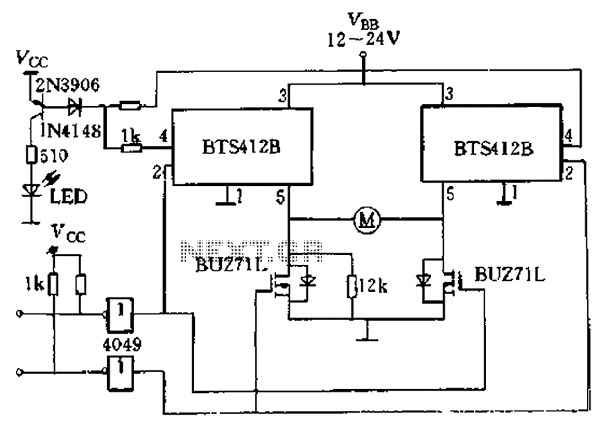
The BTS412B functions as two high-side power MOSFET switches, while two BU271L (50V, Zhang 1n) serve as low-side switches, forming a bi-directional H-bridge DC motor drive circuit. This configuration is designed for electrical automatic door systems, capable of handling...
A relatively high-power H-bridge motor controller, which is a common method to control DC motors, utilizes inexpensive TIP transistors. A continuous current of 5 Amperes through an H-bridge module may not seem significant to some, depending on their background...
The H-bridge is a circuit utilized in the electronic control of high-current devices, particularly in applications where the device's polarity needs to be reversed, such as in DC motors. The name derives from the circuit's resemblance to the letter...