
H-Bridge
The electronic circuit described serves as a control mechanism for robotic or automotive applications, specifically to manage motor functions through an H-Bridge configuration. The initial stage of the control circuit utilizes three transistors that amplify signals from an electret microphone, which is pivotal for sound detection or command execution in robotics. The amplification leads to a sufficient voltage level to charge a 47µF electrolytic capacitor, ensuring stable operation.
Following this, the circuit employs two additional transistors to generate inverted signals for the H-Bridge, allowing for bidirectional control of the motor. The H-Bridge itself, composed of four transistors, is crucial for managing the current flow to the motor, especially under load conditions. The design acknowledges the significance of torque, which is influenced by the voltage and current supplied, as well as the magnetic field strength and mechanical construction of the motor assembly.
The circuit's design ensures that it can handle various operational currents, with specific thresholds for running, starting, and loaded conditions. The transistors are selected for their ability to withstand stalled current, thus preventing damage during motor stall conditions. The requirement for careful input management is emphasized, particularly the need to avoid simultaneous HIGH signals on both inputs to prevent short-circuiting.
The circuit also features a BRAKE function, enhancing motor control by allowing for immediate cessation of motion when both outputs are equal. This is particularly useful in applications requiring quick stops. The mention of the 74C14 integrated circuit highlights the importance of matching supply voltages for optimal performance, as any discrepancy could lead to malfunction.
The design's adaptability is noted, allowing for variations in input and control voltages while maintaining functional integrity. The circuit's limitations, particularly in terms of current handling, are acknowledged, emphasizing the necessity for careful component selection to ensure reliable operation. Overall, this electronic circuit embodies a sophisticated approach to motor control in robotic applications, balancing complexity with functionality.For a project such as a robot or car, we need an ELECTRONIC circuit - one that is controlled by a "CONTROL CIRCUIT". The Control Circuit outputs a signal (or a number of signals) to control an H-Bridge. Here is a circuit of a Hex Bug. The Control Circuit consists of the first 3 transistors. These amplify the signal from the electret microphone and produce a signal that is able to charge a 47u electrolytic. The next two transistors provide inverted signals to the H-Bridge and are part of the Control Circuit. The H-Bridge consists of the last 4 transistors. 4. They all take a higher current when loaded - (the motor is driving a load). A load may be placing your fingers on the output shaft or driving through a gearbox and lifting a load or driving wheels via a gearbox.
The torque (twisting ability of the output shaft) depends on the voltage and current as well as the strength of the field magnet and the quality of construction (the closeness of the field magnet to the armature). It must also be able to deliver a "running current" (operating current) (say up to 1 amp) and a "starting current" (up to 5 amps), and a "loaded current" (up to 5 amps).
The transistors must be capable of passing a "stalled current" without being destroyed. There are a number of different H-Bridge designs and the actual circuit will depend on the number of transistors, the type of layout, the number of control lines, the voltage of the bridge, and a number of other factors. This design uses 4 transistors. Both inputs must NEVER be HIGH (this will create a short-circuit and damage the transistors). However this circuit is a good design. The voltage on the H-Bridge can be any voltage and the control voltage just needs to be higher than 1v.
The circuit provides OFF feature when both inputs are LOW but does not provide BRAKE feature. This design uses 6 transistors to do the same job as the circuit above. It does not have any advantages over the circuit above and simply uses extra components. The input voltage must be more than 1. 5v for A and B must be higher than 4v to turn off line B. When line B is less than 3. 5v, it activates the circuit. The timing of the inputs will prevent any "shoot through" current. This design requires the supply voltage to the 74C14 to be the same as the voltage on the H-Bridge (5v to 18v). The circuit provides BRAKE feature when the output of both gates are the same (either HIGH or LOW). There is a "shoot through" current during the time when the inverters change state and this occurs as follows: When the output of the gate is low, the bottom transistor is not turned on but the top transistor is fully turned ON.
When the output of the inverter rises, the top transistor is ON and the lower transistor is also turned on. When the inverter is HIGH, the top transistor is turned OFF. During the time when the inverter is changing from LOW to HIGH, both transistors are turned ON. This circuit does not have the "shoot through" current during the time when the inverters change state but it does not have the same performance as the circuit above.
The voltage on the IC and H-Bridge must be the same. The transistors are EMITTER FOLLOWERS and the voltage on the motor will be less than the voltages on the circuit above because the HIGH on the motor will be determined by the output voltage of the IC, minus the slight drop across the 1k and the voltage drop across the base-emitter junction of the transistor (a total of about 1v). The total voltage drop to the motor (due to both sides of the bridge) will be about 2v. The circuit is only suitable for a low-current motor as the 74C14 can only supply 10mA and the 1k base resistors will limit the current available through the transistors.
The resistors can be reduced to 470R. This circuit requires 4 inputs and the HIGH inputs must be about 12v. The LOW inputs need to be as close to 0v as possible. With correct timing of the inputs, no "sh 🔗 External reference
Related Circuits
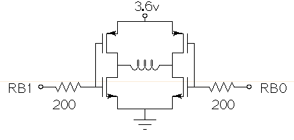
Drive a small (3.6V, <1A) brushed motor bidirectionally with a PIC microcontroller (MCU). The available space is extremely limited, so a single 3.6V power supply will be used for both the motor and the PIC, with minimal drive circuitry required. There is no dedicated motor driver IC that operates at this low voltage, making a discrete H-bridge the most suitable drive arrangement. The NXP PMV30UN and PMV32UP have been identified as suitable N-type and P-type drive MOSFETs. Since both the PIC and the motor share the same power supply, it is questioned whether it is possible to eliminate the usual driving circuitry for an H-bridge and connect the transistors directly to the MCU pins. Potential pitfalls of this approach should also be considered. To design a bidirectional motor drive circuit using a PIC microcontroller and a discrete H-bridge configuration, the following considerations must be taken into account. The H-bridge consists of four MOSFETs arranged in a configuration that allows current to flow through the motor in either direction, enabling bidirectional control. The NXP PMV30UN and PMV32UP MOSFETs are suitable candidates due to their low on-resistance and capability to operate at the required 3.6V supply voltage. The connections between the PIC MCU and the MOSFETs should be made with consideration of the gate drive requirements. Directly connecting the MOSFET gates to the MCU pins can be feasible, but it is essential to ensure that the MCU can provide sufficient gate drive voltage to fully turn on the MOSFETs. A typical threshold voltage for these MOSFETs is around 1V, so the output high level from the PIC should exceed this threshold to ensure efficient operation. It is also critical to incorporate pull-down resistors on the gate pins to prevent the MOSFETs from floating when the MCU is in a high-impedance state. This will help avoid unintended motor activation. Additionally, using gate resistors can help dampen any oscillations and limit inrush current during switching, which could potentially damage the MOSFETs or the MCU. Another consideration is the back EMF generated by the motor when it is switched off or when changing direction. This can induce voltage spikes that may damage the MCU or the MOSFETs. To mitigate this risk, flyback diodes should be placed in parallel with each MOSFET to provide a path for the back EMF, ensuring safe operation of the circuit. Thermal management is also a critical aspect of the design. Although the MOSFETs are rated for low on-resistance, continuous operation near their current limits can lead to significant heat generation. Adequate heat dissipation measures, such as heat sinks or thermal pads, should be considered. In summary, while it is possible to connect the MOSFETs directly to the MCU pins, careful attention must be given to gate drive requirements, protection against back EMF, and thermal management to ensure reliable and efficient operation of the bidirectional motor drive circuit.
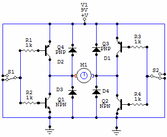
You have 4 transistors, wired as ON OFF switches. Two signal lines allow you to run the motor in one direction, when reversed, the motor runs in the other direction. It's very straightforward to use and build, but be...

A schematic for an H-bridge circuit is required to convert a 350V DC input into a 230V AC output at a frequency of 50Hz. The design should utilize a 555 timer integrated circuit (IC) along with MOSFETs. An H-bridge is...
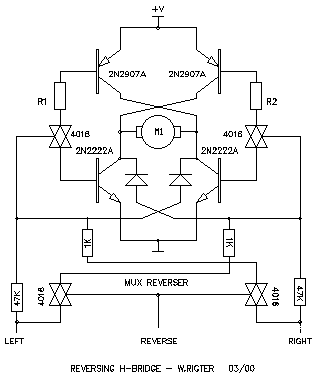
This H-bridge variant was one of the first in which the reversing circuitry is built into the driver, rather than (as is more-commonly done) into the control circuitry upstream of the driver. This is a handy circuit, though, for...
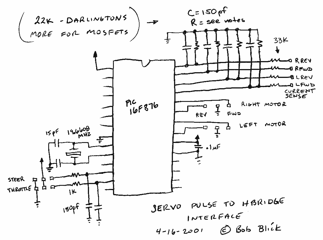
The interface uses a PIC16F876 microcontroller and not much else. It performs channel mixing, current limiting, and noise rejection. Push the stick forward, both motors move forward, move the stick to the left and the robot moves left. It...
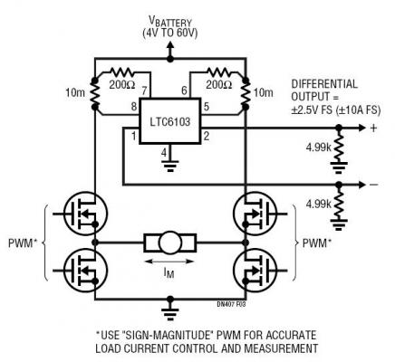
The dual outputs of the LTC6103 can be utilized independently for overload detection or combined as a differential pair to provide a bidirectional signal to an analog-to-digital converter (ADC). A typical circuit for a generic H-bridge application is illustrated....