
DC to AC inverter H-Bridge
An H-bridge is a circuit configuration that allows for the control of the polarity of a voltage applied to a load, enabling it to drive a motor or other devices in both forward and reverse directions. In this case, the H-bridge will be used to generate an alternating current (AC) output from a direct current (DC) source.
The core components of the circuit include four MOSFETs arranged in an H-bridge configuration. The MOSFETs will be responsible for switching the high-voltage DC to create a square wave output. The 555 timer IC will serve as an astable multivibrator, generating a pulse-width modulation (PWM) signal to control the gates of the MOSFETs. This PWM signal will dictate the timing and duration of the switching, effectively simulating an AC waveform.
To achieve the desired output voltage of 230V AC, the circuit must be designed to handle the high voltage and ensure safe operation. This may involve using appropriate gate driver circuits to ensure the MOSFETs switch efficiently and safely at the required frequency. Additionally, the circuit may require snubber circuits or flyback diodes to protect against voltage spikes caused by the inductive loads.
The output of the H-bridge can be further processed using a transformer to step down the voltage if necessary and to filter the waveform to produce a more sinusoidal output. Careful consideration must also be given to the thermal management of the MOSFETs, as they will dissipate heat during operation, potentially requiring heat sinks or active cooling solutions.
Overall, the design of this H-bridge circuit requires careful attention to component selection, circuit layout, and safety measures to ensure reliable operation in converting 350V DC to 230V AC at 50Hz.Hi everybody. I need H-bridge schematic for 230V 50Hz output from DC 350V, using 555 timer IC and mosfets.. 🔗 External reference
Related Circuits
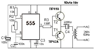
This 12V power inverter circuit can be utilized to power small devices that require 240 volts. It is particularly advantageous for operating 240-volt appliances using a 12-volt car battery. Unlike typical feedback oscillator inverters, this design employs a 555...
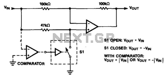
The operational amplifier (op amp) can function as either an inverter or a buffer, depending on the polarity controlled by a switch. When configured as a buffer, the gain remains constant at 1. In contrast, when functioning as an...
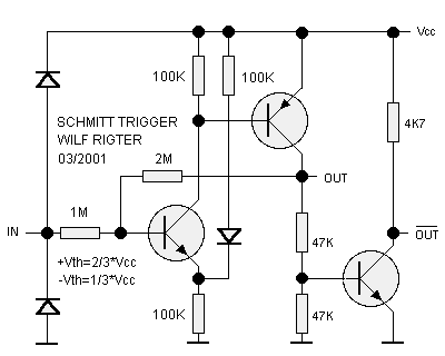
The Schmitt trigger is a specialized circuit that functions as a switch, altering its state at two distinct voltage thresholds known as the upper and lower thresholds, or the positive and negative-going thresholds. The difference between these two threshold...
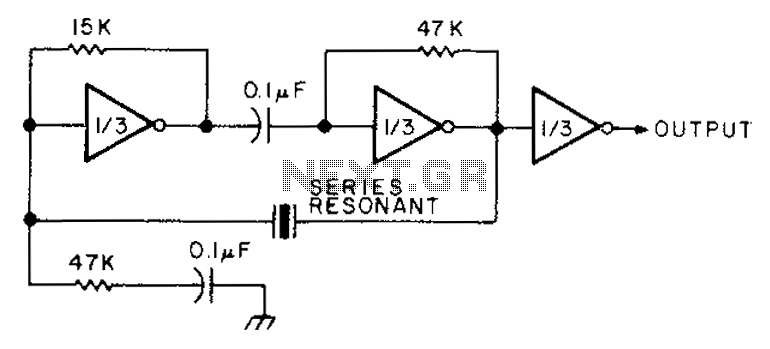
The circuit diagram illustrates the connection of all three components of the series resonant crystal and triple CD4049 inverter. The supply voltage range is between 3 to 15 volts, making it suitable for various applications. This design is compact...
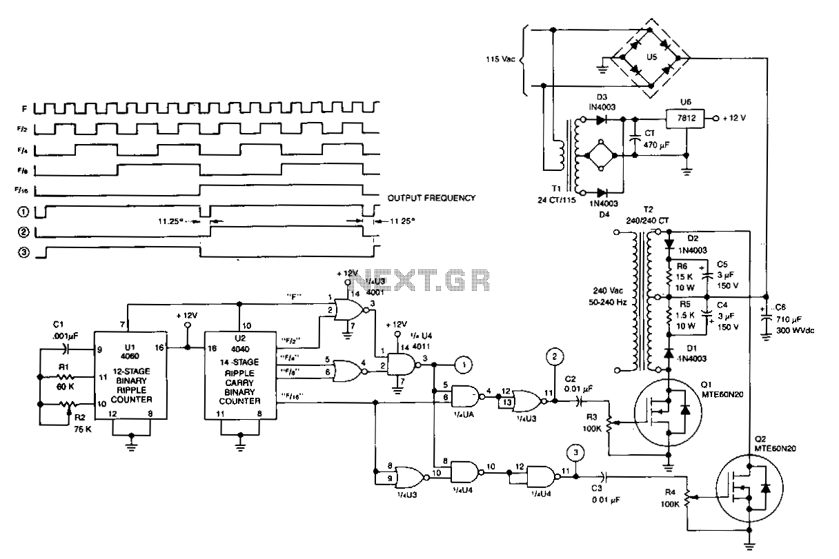
U1 is a 4060 12-stage binary ripple counter that operates as a free-running oscillator, with its frequency of oscillation calculated as 1/2.2 CIR2. The output from U1 is fed into U2, a 14-stage binary ripple counter that generates square-wave...
The LMV1090 is a fully analog dual differential input, differential output microphone array amplifier designed to reduce background acoustic noise while delivering exceptional speech clarity in voice communication applications. The LMV1090 effectively preserves near-field voice signals within 4 cm...