
H Bridge design for robotics and motion control systems
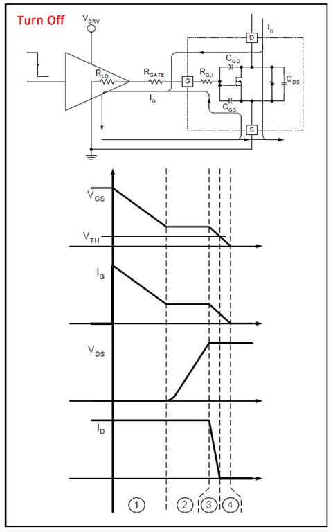
H-bridges are widely utilized in robotics and motor control applications to enable bidirectional control of DC motors. An H-bridge consists of four switches arranged in a configuration that allows current to flow in either direction through the motor, facilitating forward and reverse rotation. The low-side switch element specifically refers to the switches connected to the ground side of the motor circuit.
In a typical H-bridge configuration, two low-side switches are employed, which are often implemented using MOSFETs or bipolar junction transistors (BJTs). When one low-side switch is turned on, it completes the circuit, allowing current to flow through the motor in one direction. Conversely, activating the other low-side switch reverses the current flow, enabling the motor to rotate in the opposite direction. This control method is essential for applications requiring precise motor direction and speed control.
The low-side switch configuration offers several advantages, including simpler drive circuitry and reduced complexity in the control logic. Additionally, it helps to minimize the risk of shoot-through conditions, which can occur if both high-side and low-side switches are activated simultaneously. Proper design considerations must be made regarding the gate drive signals to ensure that the switches are turned on and off at the appropriate times, preventing damage to the components and ensuring efficient operation.
In summary, the low-side switch element in an H-bridge plays a critical role in the effective control of motors in robotic applications. Its ability to manage current flow direction is fundamental to achieving the desired motion control, making it a vital component in modern robotics and automation systems.H bridge applications for robots, robotics, and motor control. This post focuses on the low side switch element. 🔗 External reference
Related Circuits
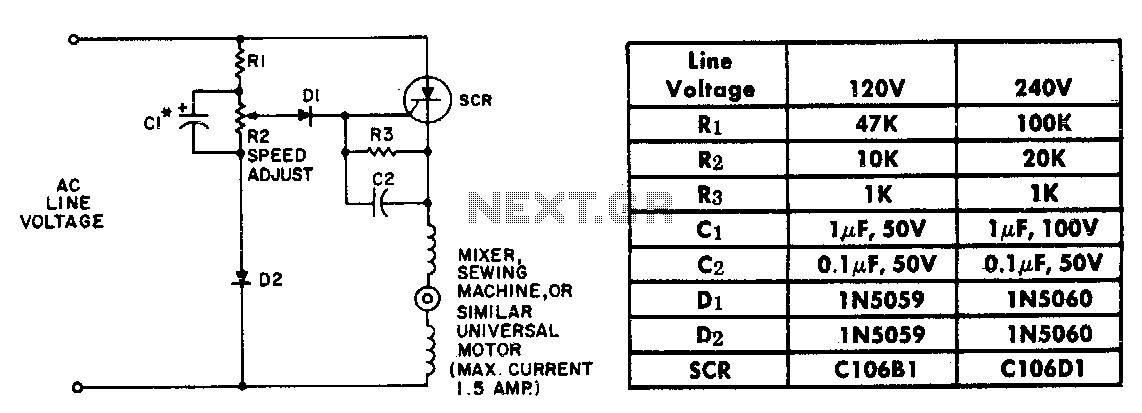
The resistor-capacitor network R1-R2-C1 generates a ramp-type reference voltage that is superimposed on an adjustable DC voltage controlled by the speed-setting potentiometer R2. This reference voltage, available at the wiper of R2, is compared against the residual counter electromotive...
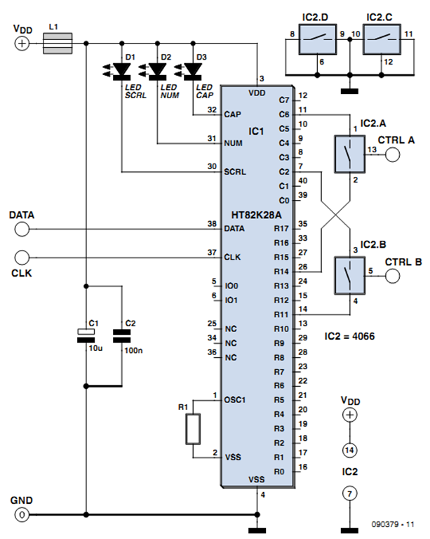
One of the more challenging aspects of creating a control or security system that utilizes a PC, such as a burglar alarm, is connecting the sensors to the computer. This typically requires specialized interface expansion boards, and programming that...
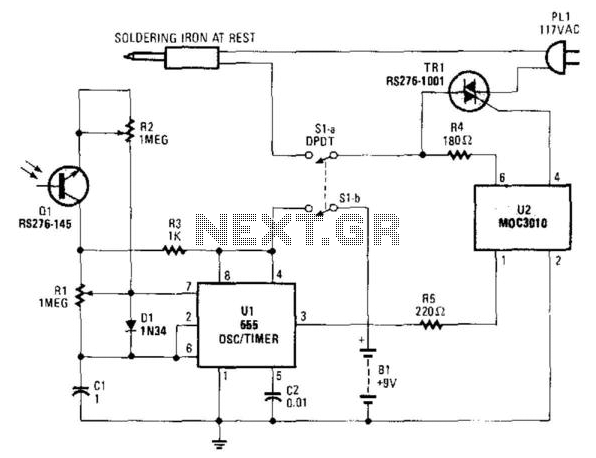
An infrared-sensitive phototransistor is employed to detect the temperature of a soldering iron. The phototransistor must be positioned to view the tip through an opaque tube to prevent interference from stray light, and it is advisable to equip the...
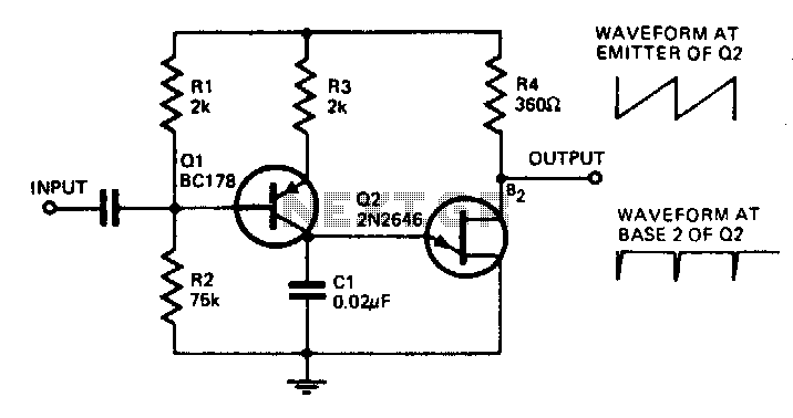
With the component values shown, the oscillator has a frequency of 8 kHz. When an input signal is applied to the base of Q1, the current flowing through Q1 is varied, thus affecting the time required to charge C1....
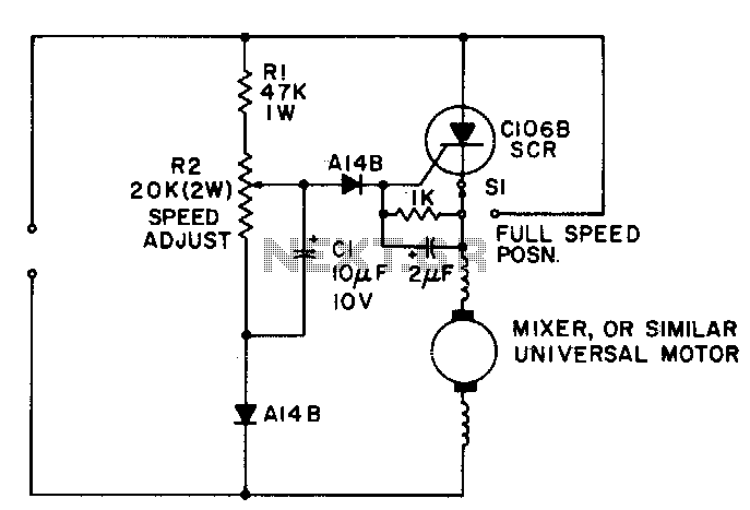
A simple half-wave motor speed control is effective for use with small universal (AC/DC) motors, featuring a maximum current capability of 2 amps RMS. The control provides speed-dependent feedback, ensuring excellent torque characteristics for the motor, even at low...

The adjustment control for the contrast of an LC-Display is typically a 10-k potentiometer. This functions effectively as long as the power supply voltage remains constant. However, in scenarios where the power supply voltage fluctuates, such as with battery-operated...