
Light Switch
This light-activated relay circuit utilizes a light-dependent resistor (LDR) as the primary sensing element. The LDR changes its resistance based on the ambient light level; it has a low resistance in bright light and high resistance in darkness. This characteristic is leveraged to control a relay, which can switch on or off a connected load, such as a lamp or other light fixtures.
The circuit typically consists of the following components: an LDR, a variable resistor (VR1) for sensitivity adjustment, a relay, a transistor to drive the relay, and an LED indicator for visual feedback. The LDR is connected in a voltage divider configuration with VR1, allowing for fine-tuning of the circuit's response to light levels.
When the light intensity exceeds a certain threshold, the resistance of the LDR decreases, causing the voltage across it to drop. This change is detected by the transistor, which then activates the relay, closing the circuit and powering the connected load. Conversely, when the light level falls below the set threshold, the LDR's resistance increases, leading to a higher voltage across it, turning off the transistor and deactivating the relay.
The LED indicator is connected in parallel with the relay and will illuminate when the relay is activated, providing a clear visual indication of the circuit's status. The sensitivity adjustment via VR1 allows the user to set the desired light level at which the relay should activate, making the circuit versatile for various applications, such as automatic lighting in dark environments or security lighting systems.
Overall, this circuit offers a practical solution for automated light control, enhancing convenience and energy efficiency in lighting applications.Light Switch. This is a light switch or light activated relay circuit.The relay if LDR uncoverd and relays, if LDR VR1 covered.
Related Circuits

The timer is activated by the zero-crossing voltage pulse. The time constant is defined by the combination of C5 and the resistors R14 and R15, which determines the conduction angle. The transistors T2 and T3 prevent the power switch...
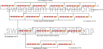
The following article outlines a sophisticated LED sequencing and diverging ring light that can serve as a tail brake light in vehicles. This circuit concept was proposed by a dedicated reader, Mr. Bobby. The design aims to create a...
A 2003 Monte Carlo SS is experiencing issues with low idling, causing the engine to stall while driving or when parked. Additionally, the dashboard lights are malfunctioning; they occasionally activate for a brief moment before turning off again. There...
A 1996 Ford Explorer has non-functional headlights. The vehicle has operational low beams and interior lights. The owner has replaced the bulbs, checked the fuses, relays, and light switch, yet the headlights remain inoperative. Suggestions are requested to identify...
This device is a simple timer that keeps the headlights of a vehicle on for approximately 1 minute and 30 seconds, allowing access to dark areas without the need to manually switch off the lights. Activating switch P1 initiates...
With the increase in the variety of modern electrical equipment for vehicles and the rise in power levels, there is a growing demand for different types of power supplies, including AC and DC sources. The power system needs to...