
Hall effect sensor as Toilet Tank Refiller

The described system utilizes a 12 Volt power supply sourced from either a solar panel or a wall-wart power adapter, ensuring flexibility in energy sourcing. The core functionality revolves around a water pump responsible for transferring water from a cistern located below the toilet tank to the tank itself. This operation is contingent upon the water level within the toilet tank, activating the pump when the tank is empty and deactivating it once the tank reaches its full capacity.
At the center of this control mechanism is a Panasonic hall effect sensor, which detects the presence of a magnetic field. The sensor's output behaves as a digital switch; it pulls low (to ground) when exposed to a magnetic field, indicating that the tank is empty and the pump should activate. Conversely, when the magnetic field is removed, the output returns high, signaling the pump to turn off once the tank is filled.
To implement this system, a basic schematic would include the following components: a 12 Volt power supply, the hall effect sensor connected to the control circuitry, a relay or transistor to drive the pump, and the pump itself. The hall effect sensor would be positioned such that a magnet attached to the float mechanism in the toilet tank activates the sensor when the water level is low. The relay or transistor would serve as a switch to control the pump's operation based on the sensor's output.
In terms of safety and efficiency, it is advisable to integrate a fuse in the power supply line to protect against overcurrent conditions. Additionally, using a diode across the relay coil can prevent back EMF from damaging the control circuitry when the relay is deactivated. Overall, this system design ensures reliable operation of the pump while maintaining energy efficiency in a sustainable manner.The 12 Volt power in my application comes from a small solar power system, it may also be provided by a suitable wall-wart DC power supply. The cistern is located below the toilet tank, the pump moves the water up to the toilet`s tank. The pump is switched on when the toilet tank is empty, it is switched off when the tank has filled. The Panasonic hall effect sensor is the heart of the system. The hall effect sensor`s output pulls to ground when in the presence of a relatively strong magnetic field. When the magnet is pulled away from the hall effect sensor, the output goes high 🔗 External reference
Related Circuits
This very simple circuit acts as a high sensitivity capacitive sensor. Lamps and/or Buzzers are operated at half the mains supply voltage when a part of the human body comes in contact with the sensor or approaches it at...
If a sensor is resistive, an alternating current (AC) is equivalent to pulsed direct current (DC), and the sensor will degrade based on the root mean square (RMS) value of the AC signal. Applying 1V AC RMS is effectively...
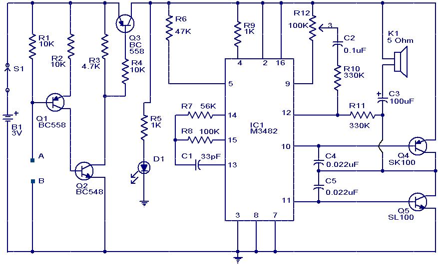
This circuit is a simple musical alarm that generates a tone when water or another conductive liquid touches the two sensor wires provided. It utilizes four transistors and a melody generator integrated circuit (IC) M3482. When water bridges the...
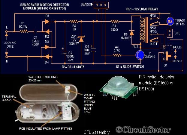
This circuit diagram is based on the PIR motion sensor module BS1600 (or BS1700) designed for security lighting in power-saving mode. If the component is unavailable in local stores, it can be purchased online. A key advantage of this...

The main component of the circuit has been achieved using an integrated circuit (IC) with a significant number of bulk components, primarily capacitors. The internal circuit is designed to output from the differential amplifier using a PNP unipolar configuration,...
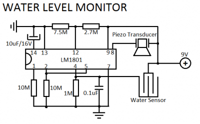
LM1801 Water Level Sensor Circuit Diagram. Features: reference voltage is overshot, and the IC drives the ceramic transducer to beep, low power consumption. The LM1801 water level sensor circuit utilizes the LM1801 integrated circuit, which is designed to monitor water...