
Interfacing MSP430 to analog AC-rated humitidy resistive sensor HCZ-H8
A comprehensive electronic schematic for the described circuit would consist of a resistive sensor, a microcontroller (MSP), a digital-to-analog converter (DAC), an analog-to-digital converter (ADC), and a constant current source. The resistive sensor will be connected to the current source, which is controlled by the MSP port pin. The current source can be implemented using a transistor or an operational amplifier configured to provide a constant current output. A timing circuit, possibly utilizing a timer interrupt or a direct memory access (DMA) transfer, will allow for precise control of the sampling intervals, ensuring that the current is applied for a specified duration before being turned off.
The DAC will generate the necessary voltage signals for testing and calibration purposes, while the ADC will be used to capture the voltage across the sensor during sampling. A calibration table stored in the microcontroller's memory will facilitate the conversion of voltage readings to temperature values. The circuit should also include necessary protection components, such as diodes to prevent reverse polarity and capacitors to filter out noise.
Power supply considerations are essential, as the circuit may require a stable voltage reference for accurate measurements. The design may also incorporate a feedback mechanism to adjust the current source based on real-time readings, ensuring consistent performance across varying environmental conditions. This comprehensive approach will allow for accurate and efficient measurements from resistive sensors while minimizing potential degradation and ensuring reliability in data acquisition.Hmmm, if it is resistive, AC is equivalent to pulsed DC and the sensor is degraded in any case with the RMS value of the AC signal. If you appy 1VAC RMS, you could as well apply 1V DC. If you use an ADC10 or ADC12, the samples are take one after another (also for most devices with an SD16, only the devices for energy metering support simultaneous
sampling). And if you`re already samling one after another and have to calculate the time shift, you can as well just sample the result, as it was you who created the input signal with the DAC, so you KNOW the input voltage (calibration provided). For resistive sensors, however, I would go a different approach: set up a small constant current source that can be switched on and off by an MSP port pin.
Every millisecond switch it on, take a sample of the resulting voltage across the sensor, then switch it off again, to avoid sensor heating. if your current source forces 1mA through the sensor and the voltage reading is 1V then the sensor resistance is 1kOhm.
I guess the calibration table takes the sensor heating caused by the measuring voltage into account. but only for a given environment temperature. To simulate it, calculate the power applied to the sensor under the the conditions of the calibration table, and apply a constant current that causes the same power loss on the sensor. The readings should be equal. Then the current source does not need to be switche on and off (except to save power, but then the first readings after turnign it on again will be inaccurate) and things are even easier: read teh voltage and convert it into a temperature by a table.
Before posting bug reports or ask for help, do at least quick scan over this article. It applies to any kind of problem reporting. On any forum. And/or look here. If you cannot discuss your problem in the public, feel free to start a private conversation: click on my name and then `start conversation`. But please do so only if you really cannot do it in a public thread, as I usually read all threads. And I prefer to answer where others can profit from it (or contribute to it) too. Okay, that`s a possibility. I don`t know why a resistive sensor might become polarized, but it might have electrochemical reasons (e.
g. the water molecules being separated to H and O2, and for a DC compoenent this will give an uneven distribution of the two on the electrodes- if there is such a thing). I think that in your approach 1mA of DC periodically applied to the sensor will not degrade it too much as it will self depolarize during the period of inactivity.
Or you can apply inverted pulses. However, AC power supply reauires either a negative voltage somehow generated (the DAC will only generate positive voltages relative the MSp GND) or the device provided with a virtual ground that is effectively a stabilized voltage hovering in the middle of the measurement range. This consumes power. IIRC, Ithis remark was referring to the setup with a DAC generated waveform. It`s noteasy to generate a sinusodial wave generation of a fixed frequency if you set a value and then sample it and then set the next, in this order.
(this would rather be done with a timer interupt that controls the DAC output, or a timed DMA transfer), but I on`t think it`s necessary to keep a sinusodial waveform and timing at all. But then, if you just apply a voltage and then measure, you already know the voltage you applied. You only need to sample the result. If you worry about possible calibration issues: sampling two voltages would be from two different input channels, and calibrations differences between the two channels would affect your result too.
If you apply the current pulse, then of course you have all the time until the pulse ends (which you control) to take the two samples. But where to get the second sample from You do not apply a voltage, you apply a current. So there is only one voltage to be sampled: the 🔗 External reference
Related Circuits
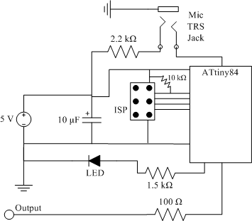
The clap sensor is a straightforward circuit that consists of a PC microphone, a microcontroller, and an output. The circuit design features the ATtiny84 microcontroller, chosen for familiarity with the AVR architecture and accessibility to necessary tools. The ATtiny84...
The following circuit illustrates an Ultrasonic Sensor Switch circuit diagram. This circuit is based on the 555 Timer IC for the Ultrasonic Transmitter. The Ultrasonic Sensor Switch circuit utilizes a 555 Timer IC configured in astable mode to generate ultrasonic...
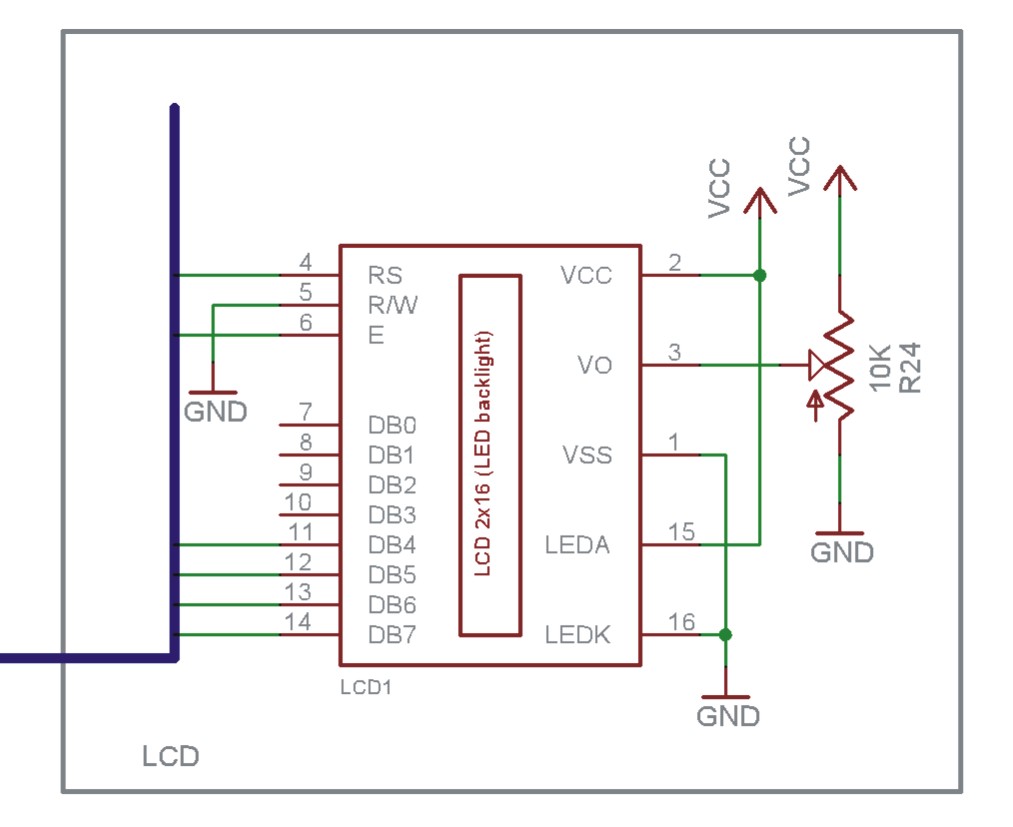
The EN line is referred to as 'Enable'. This control line is utilized to indicate to the LCD that data is being sent. To transmit data to the LCD, the program must ensure that this line is low (0),...
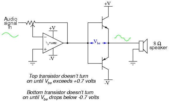
This project is an audio amplifier designed to amplify output signals from small radios, tape players, CD players, or other audio signal sources. For stereo operation, two identical amplifiers must be constructed—one for the left channel and another for...
The following circuit illustrates the CD4017 integrated circuit (IC) used in an automatic room lights sensor circuit diagram. Features include a single light sensor utilizing two light-dependent resistors (LDRs). The CD4017 is a decade counter IC that can drive multiple...

This design idea explains how to develop a water sensor circuit that can monitor upper and lower water levels. The water sensor circuit is designed to detect and monitor water levels within a specified range, providing feedback when the water...
Warning: include(partials/cookie-banner.php): Failed to open stream: Permission denied in /var/www/html/nextgr/view-circuit.php on line 713
Warning: include(): Failed opening 'partials/cookie-banner.php' for inclusion (include_path='.:/usr/share/php') in /var/www/html/nextgr/view-circuit.php on line 713