
water sensor alarm circuit using ic
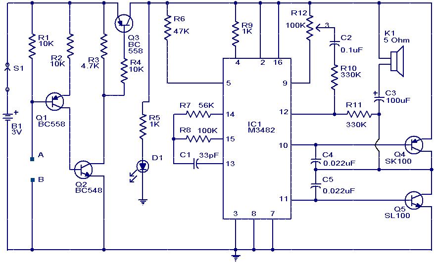
The musical alarm circuit operates based on the principle of conductivity detection. The two sensor wires (A and B) are strategically positioned to detect the presence of water. When a conductive liquid completes the circuit between these two points, it triggers the activation of transistor Q1. This transistor acts as a switch that connects the ground to the base of Q2 and Q3, thereby turning them ON.
Transistor Q2 serves as a current amplifier, ensuring that sufficient current flows to Q3. The role of Q3 is critical, as its activation provides the necessary power to the melody generator IC M3482. This IC is designed to produce a variety of melodies, and it is pre-programmed to cycle through 12 different tunes. The output of the IC is connected to a speaker or buzzer, which converts the electrical signals into audible sound.
The use of the potentiometer R12 allows for user-adjustable volume control, enabling the user to set the desired sound level of the alarm. This feature enhances the usability of the circuit in various environments, catering to different sound requirements.
In summary, this circuit effectively combines simple electronic components to create an engaging musical alarm system that activates in the presence of water, making it suitable for applications such as leak detection or as an alert system in wet environments. The design is straightforward, making it accessible for hobbyists and those interested in learning about basic electronics.This is a simple musical alarm circuit that produces a musical tone when water or some conducting liquid comes in contact with the 2 sensor wires provided. The circuit relies on four transistors and one melody generator IC M 3482. When water comes in contact with the sensors wires A & B, the bottom of Q1 gets connected with the negative and it con
ducts. This makes Q2 and Q3 ON. When Q3 is ON the power is offered for the music generator circuit and it starts producing 12 completely different melodies one after another. The music continues as long as there`s water between the sensor wires. The POT R12 will be used as a volume controller. 🔗 External reference
Related Circuits

Sensing short circuits in equipment that operates underwater is particularly important. The wet-mat connector design shown in Figure 20-4 is also suitable for other remote short-circuit sensing applications. Due to the limitations imposed by the battery and voltage levels,...
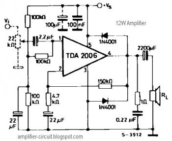
The power amplifier IC TDA2006 provides high output current and has very low harmonic and cross-over distortion. Furthermore, the device incorporates an original (and patented) short circuit protection system that automatically limits the dissipated power to keep the working...

The schematic below illustrates four methods of controlling a relay with a digital logic signal. Figure A can be used in most cases where the relay coil requires 100 mA or less and the input current is 2 milliamps...
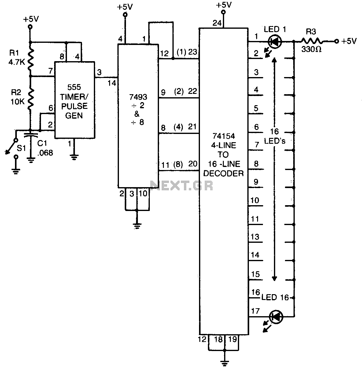
The 555 timer generates a rapid series of pulses when switch SI is in the open position. These pulses are grouped into sets of 16 and converted into binary format by the 7493 counter. The binary output is then...

The passive tone control circuit is designed to adjust the bass without expansion, utilizing resistors (R) and capacitors (C). It functions as a frequency filter and is easy to construct, requiring no external power supply. This circuit can be...

The circuit is constituted by the RF2324 1880MHz internal amplifier collector bias application. A radio frequency (RF) signal enters through input pin 3 and is processed by a preamplifier. The final stage power amplifier output is amplified by 7...