
Halloween game with moving sensor (12F683)
Every time the circuit is powered on, the microcontroller stores the distance read by the Sharp sensor and uses this as a reference for the space available for object/people detection. Anything moving in front of the sensor up to that reference activates the first stored sound.
The other 3 sounds are time-triggered only when the light is out. The LDR senses the light intensity and only when placed in darkness will it activate the remaining sounds. Sometimes the sounds are individually played and sometimes combined. There are 4 sound slots available with a maximum length of 6 seconds each.
The PCB has some connectors with jumpers, making it possible to change from record to playback mode and vice versa.
Connector #1, named REC/PLAY, is a 3-pin connector, and jumper connection must be placed to the left side for record mode or to the right side for playback mode.
Also, connector #2, named Jumpers, must have 2 jumpers installed for playback mode. This is responsible for the memory address of the sounds.
When in record mode, some wire jumper connections must be made to change the address of the recordings manually by connecting pin 2 and 3 to VDD or VSS according to the table below:
For VDD and VSS connections, it is possible to use a connector named + -.
Recording: With power off, connect a microphone, move jumper to record mode and connect message pin 2 and pin 3 to VSS.
Turn on the power and prepare the sound you wish to record for #1 sound. Press and keep the S1 push button while recording. Release the button to stop recording. Connect pin 2 to VDD and keep pin 3 to VSS - this will address sound #2. Press and keep the S1 push button while recording. Release the button to stop recording. Connect pin 2 to VSS and pin 3 to VDD - this will address sound #3. Press and keep the S1 push button while recording. Release the button to stop recording. Connect pin 2 to VDD and keep pin 3 to VDD - this will address sound #4. Press and keep the S1 push button while recording. Release the button to stop recording. Turn the power off, disconnect the microphone, restore address jumpers and move jumper to playback mode.
Parts:
R1 10K ohms resistor
R2 1K ohms resistor
R3 100K ohms resistor
R4 5K1 ohms resistor
R5 470K ohms resistor
R6 10K ohms resistor
R7 10K ohms resistor
R8 1K ohms resistor
LDR Light dependent resistor
C1 100nF capacitor
C2 100nF capacitor
C3 100nF capacitor
C4 100nF capacitor
C5 10uF capacitor
C6 22uF capacitor
C7 220uF capacitor
C8 4.7uF capacitor
SENSOR GP2D12 from Sharp
IC1 12F683 microcontroller from Microchip
IC2 ISD 2532 from Winbond
S1 Push button
SP Speaker
MIC Electret microphone
Others:
Box
PCB
Jumpers
4.8V Battery Pack
Hex program for the microcontroller
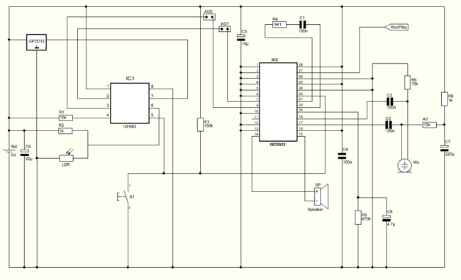
This circuit design serves as an interactive Halloween prop, combining sound playback with motion and light sensing capabilities. The Sharp GP2D12 sensor is utilized for motion detection, providing a distance measurement that informs the microcontroller when to trigger sound playback. The light-dependent resistor (LDR) is integrated to enhance the experience by activating additional sounds in low-light conditions, creating an eerie atmosphere.
The microcontroller, a Microchip 12F683, is programmed to handle the logic for monitoring the sensor inputs and controlling the sound chip, the ISD 2532 from Winbond. The sound chip is capable of recording and storing up to four sounds, each with a duration of up to 6 seconds. The recording process is facilitated through the use of a microphone and a set of jumper connections that allow the user to specify which sound slot is being recorded.
The printed circuit board (PCB) is designed to accommodate all components and provide necessary connections, including jumper configurations for switching between record and playback modes. The inclusion of various resistors and capacitors ensures stable operation and signal integrity throughout the circuit.
The circuit is powered by a 4.8V battery pack, providing sufficient energy for the components while maintaining portability. A push button (S1) is incorporated for manual control during the recording phase, allowing users to easily capture sounds for playback.
Overall, this design encapsulates a creative approach to enhancing Halloween festivities through interactive electronics, ensuring a memorable experience for visitors.Halloween is coming up and it's time to do some pranks. Everyone likes Halloween and I'm no exception. Every year me and my wife decorate the house with lot's of bugs, spider webs, creepy posters and of course lot's of Halloween candy. While making the normal Halloween preparations I came up with the idea of making a circuit that would make some scary noises and also would react to movement.
I expect to get some screams and laughs from friends that come to visit us this year. The circuit is basically a sound chip that records and stores sounds in memory and plays them back with a microcontroller and it's triggered by light and motion. The sound chip is from maker winbond and has a very good sound quality. This circuit has 2 sensors. One motion sensor ( Sharp GP2D12 ) and a light sensor ( LDR ). The microcontroller monitors both sensors and triggers the sound chip in certain conditions. Every time the circuit is powered on, the microcontroller stores the distance read by the sharp sensor and uses this as reference for the space available for object/people detection. Anything moving in front of the sensor up to that reference activates the first stored sound. The other 3 sounds are time triggered only when the light is out. The LDR senses the light intensity and only when placed in darkness it will activate the remaining sounds.
Sometimes the sounds are individually played and sometimes combined. There are 4 sounds slots available with max. length of 6 seconds each. The PCB has some connectors with jumpers making it possible to change from record to playback mode and vice versa. Connector #1 named REC/PLAY is a 3 pin connector and jumper connection must be placed to the left side for record mode or to the right side for playback mode.
Also connector #2 named Jumpers must have 2 jumpers installed for playback mode. This is responsible for the memory address of the sounds. When in record mode, some wire jumper connections must be made to change the address of the recordings manually connecting pin 2 and 3 to VDD or VSS according to table bellow: For VDD and VSS connections it's possible to use connector named + - Recording: With power off, connect a microphone, move jumper to record mode and connect message pin 2 and pin 3 to VSS. Turn on the power and prepare the sound you wish to record for #1 sound. Press and keep the S1 push button while recording. Release the button to stop recording. Connect pin 2 to VDD and keep pin 3 to VSS - this will address sound #2. Press and keep the S1 push button while recording. Release the button to stop recording. Connect pin 2 to VSS and pin 3 to VDD - this will address sound #3. Press and keep the S1 push button while recording. Release the button to stop recording. Connect pin 2 to VDD and keep pin 3 to VDD - this will address sound #4. Press and keep the S1 push button while recording. Release the button to stop recording. Turn the power off, disconnect microphone, restore address jumpers and move jumper to playback mode. Parts: R1 10K ohms resistor R2 1K ohms resistor R3 100K ohms resistor R4 5K1 ohms resistor R5 470K ohms resistor R6 10K ohms resistor R7 10K ohms resistor R8 1K ohms resistor LDR Light dependent resistor C1 100nF capacitor C2 100nF capacitor C3 100nF capacitor C4 100nF capacitor C5 10uF capacitor C6 22uF capacitor C7 220uF capacitor C8 4.7uF capacitor SENSOR GP2D12 from Sharp IC1 12F683 microcontroller from Microchip IC2 ISD 2532 from winbond S1 Push button SP Speaker MIC Electret microphone Others: Box PCB Jumpers 4.8V Battery Pack Hex program for the microcontroller
🔗 External reference
Related Circuits

555 precision temperature sensor with temperature frequency converting circuit diagram consisting of: The 555 precision temperature sensor operates by converting temperature variations into frequency signals. This circuit typically utilizes a 555 timer IC configured in astable mode to generate...
This line-following robot sensor, also known as a surface scanner for robots, is a compact, stamp-sized infrared proximity detector designed for short-range detection, typically within 5 to 10 mm. The line-following robot sensor operates using infrared light to detect the...
An affordable electronic device useful for demonstrating electrostatic phenomena. Ahern's instrument serves as an effective substitute for the tonal electrostatic voltmeter. It provides polarity-dependent information about electric charge motion that conventional instruments do not offer. This apparatus is easy...
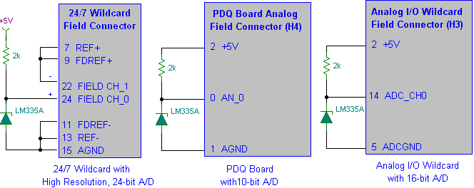
Interfacing the LM335A temperature sensor with A/D converters involves measuring temperature using the LM35 and LM335A sensors alongside the 9S12 HCS12 microcontroller. This process includes analyzing both calibrated and uncalibrated temperature errors of integrated circuit temperature sensors. The LM335A is...
This is a simple electronic thermometer circuit. It is an inexpensive circuit because the probe or sensor used in this circuit is a 2N2222 silicon transistor. The electronic thermometer circuit utilizes the 2N2222 silicon transistor as a temperature sensor. The...
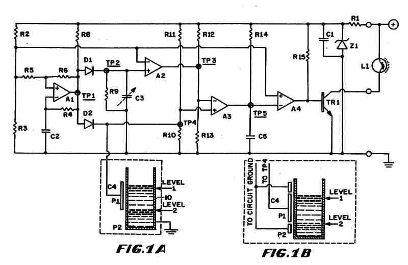
Figure 1 (A) depicts the circuit diagram of one embodiment of the fluid level detector designed. The circuit is typically powered by a 12-volt automobile battery, which is reduced to a 5-volt DC source using a voltage regulator consisting...