
Moving Charge Sensor of J. Ahern
This electronic instrument is designed to provide a practical and educational tool for exploring electrostatic principles. The compact design and ease of assembly make it accessible for educational purposes, enabling students and enthusiasts to engage with concepts of charge movement and polarity in a hands-on manner. The use of a CMOS NAND gate integrated circuit as the primary component leverages the inherent sensitivity of CMOS technology, allowing for precise detection of charge movement. The visual indicators (LEDs) provide immediate feedback, making it easy to observe the effects of static electricity in real time.
The choice of a telescoping antenna as a sensing electrode enhances the instrument's usability, allowing for easy storage and deployment. The instrument's sensitivity to the movement of charge, rather than merely its presence, opens up opportunities for demonstrations and experiments that illustrate dynamic electrostatic phenomena. Furthermore, the design's low power consumption ensures longevity in battery life, making it suitable for extended use in educational settings or demonstrations.
Overall, Ahern's instrument stands out as a versatile and effective tool for teaching and understanding electrostatic principles, providing an engaging way to visualize and measure electric charge dynamics. The simplicity of its design, combined with the effectiveness of its operation, makes it an invaluable addition to any educational toolkit focused on electronics and physics.An inexpensive electronic instrument useful in demonstrating electrostatic phenomena. First, Ahern`s instrument can be employed as an inexpensive and effective substitute for the tonal electrostatic voltmeter. Second, the instrument provides polarity-dependent information about electric charge motion that other, more conventional instruments do not provide.
Third, this apparatus is a very easily built electronic-based instrument for monitoring static charge. What distinguishes Ahern`s instrument from other charge detection and measurement apparatuses used in electrostatics demonstrations, such as the conventional leaf electroscope and the tonal electrostatic voltmeter, is that Ahern`s device responds to the movement of positive (+) and negative (-) electric charge toward or away from a sensing electrode. As such, the instrument is probably most closely akin to some of the electrostatic charge monitors now commercially available and routinely installed in electronics assembly areas to detect conditions that might cause damage to sensitive electronics components during assembly.
The instrument is small and portable, it operates on a 9 volt battery, and the output is visual. Furthermore, its construction requires only minimal skills with a soldering iron and other simple tools, and it can be packaged very conveniently in a small, shielded box. Refer to the photo at the left. A short, telescoping cellular telephone antenna mounted so that it retracts into the box when not in use, serves as a sensing electrode.
The instrument is sensitive primarily to the movement of charge rather than to its presence. Thus, when the approach of negative charge is sensed, the green LED comes on, while the red LED lights if positive charge is approaching. As negative charge starts to recede from the sensing electrode, the green changes to red, while red changes to green as positive charge recedes.
If a condition of balance can be achieved between positive and negative, then both LED`s can be made to light up; this balance is exquisitely delicate due to the very high input impedance of the cmos gates. In the absence of any charge, neither LED lights up. The instrument is much more sensitive than most hand-held charge detectors. During demonstrations of electrostatic phenomena - for example, triboelectrification - the moving charge sensor can be used to sense the charge and to determine its sign.
The circuit draws very little current, so the instrument can be operated for extended periods of time without draining the battery. The heart of this inexpensive circuit, the schematic of which is shown below, is a quad cmos NAND gate integrated circuit (4011).
Experienced circuit designers will smile when they recognize that this circuit beneficially exploits the notorious static sensitivity of cmos IC devices. Only three of the four NAND gates in the IC are actually used in the instrument; the input of the fourth gate should be grounded.
The 3 MW series resistor protects the chip from ESD damage, while the capacitors serve the primary function of biasing the gates to a quiescent state. Resistors in the ~10 GW range may be used instead, but the capacitors - Ahern specifies tubular ceramics - with their very small but not negligible leakage current, work just as well and are definitely cheaper and more readily available.
In addition, the charge storage feature of the capacitors introduces some incidental phase lag between the two detection circuits that permits both LEDs to remained lig 🔗 External reference
Related Circuits
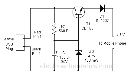
A mobile phone can be charged using the USB outlet of a PC. This simple USB cellphone charger circuit provides a regulated output of 4.7 volts for charging the mobile phone. The USB outlet typically supplies 5 volts DC...
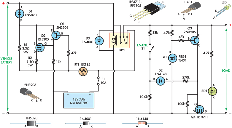
The SLA battery is charged from the vehicle's battery. When the engine is running, the voltage remains fairly constant, which greatly simplifies the charging circuit. If the SLA battery is fully charged, any further charging current from the vehicle...

The circuit described utilizes an IRF840 MOSFET, which has a maximum drain-source voltage (DSV) rating of 500V. The avalanche voltage is calculated to be approximately 365V, indicating that inductive kickback voltage can reach up to about 600V in the...
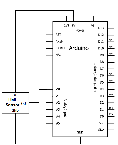
The Hall effect sensor utilized in this circuit is the A1302 Hall effect sensor manufactured by Allegro. This integrated circuit (IC) is capable of detecting magnetic fields. It will be connected to an Arduino, allowing the Arduino to read...

This sensor switch circuit features nine channels and consists of three integrated circuits along with several resistors. The 74HC147, which has a high input impedance, enables the use of 4.7 MΩ resistors to establish a logic level "high" for...
The Current Sensor Board features an Atmel AVR AT90S8535 microcontroller operating at 8 MHz. It samples six ADC current inputs and utilizes the remaining two ADC inputs for controlling an integrating charge counter. The processed results are encapsulated into...
Warning: include(partials/cookie-banner.php): Failed to open stream: Permission denied in /var/www/html/nextgr/view-circuit.php on line 713
Warning: include(): Failed opening 'partials/cookie-banner.php' for inclusion (include_path='.:/usr/share/php') in /var/www/html/nextgr/view-circuit.php on line 713