
Ham Band Vfo Circuit
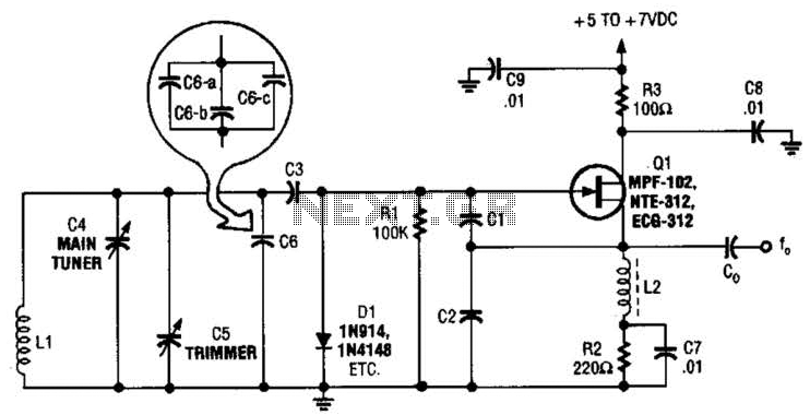
The VFO circuit is implemented using a Colpitts oscillator, which is characterized by its use of a combination of capacitors and an inductor to generate oscillations. The frequency of oscillation is primarily influenced by the values of the capacitors (C2, C3, C4, C5, and C6) and the inductor (L1). In this configuration, the quality of oscillation can be enhanced by selecting appropriate capacitor values that allow for fine-tuning of the output frequency.
The choice of capacitor values is critical; for instance, using 70 pF capacitors for higher frequencies (5 to 5.5 MHz) provides a stable oscillation, while a larger capacitor (1000 pF) is necessary for lower frequencies (3.5 to 4.0 MHz) to maintain the oscillator's functionality. The variable capacitor C3, which can be adjusted between 10 to 220 pF, allows for further frequency modulation, providing flexibility in tuning the oscillator to the desired frequency.
Capacitor C6's ability to be composed of multiple smaller capacitors in parallel is advantageous for achieving precise capacitance values. This method allows for fine-tuning and can accommodate the specific requirements of the circuit, ensuring optimal performance across the specified frequency range. Proper selection and arrangement of these components will lead to a reliable and stable VFO suitable for amateur radio applications. This basic VFO for the 3- to 6-MHz range is coirimonly used in amateur applications, using a Colpitis circuit. For 5 to 5.5 MHz, C = C2 = 70 pF and for 3.5 to 4.0 MHz, use 1000 pF. C3 is typically 10 to 220 pF, depending on the frequency. C4, C5, and C6, together with C3, determine the frequency along with LI. C6 can be made up of several smaller values, paralleled to get the exact required value. 🔗 External reference
Related Circuits
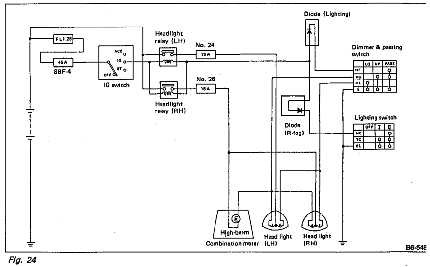
Understanding the headlight wiring in a car involves examining the purpose of two diodes in the circuit diagram. The circuit allows for two independent methods of activating the light relays: through the light switch or by flashing the high...
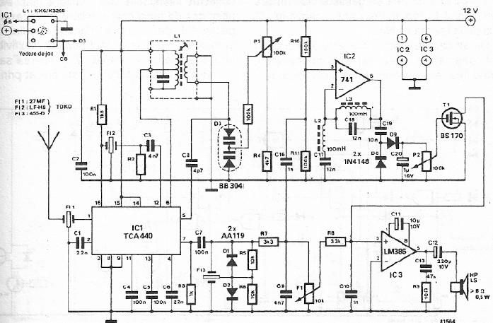
A simple FM CB radio receiver can be constructed using the electronic diagram provided. This FM CB radio receiver circuit utilizes a TCA440 integrated circuit and operates at an intermediate frequency of 455 kHz. The input filter is a...
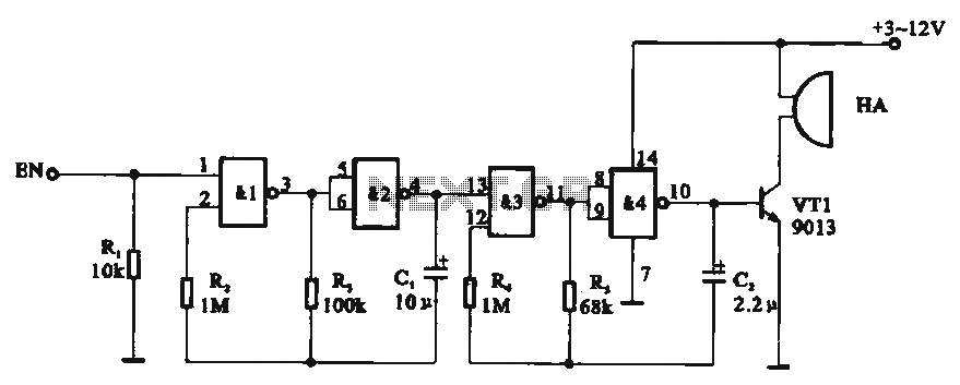
Tone generator circuit. The tone generator circuit utilizes a quad 2-input NAND gate integrated circuit, specifically the CD4011. NAND gates 1 and 2, along with NAND gates 3 and 4, form two gating multivibrator oscillators. The oscillation period of...
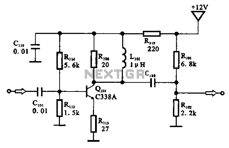
The amplifier circuit is designed as a pre-amplifier configuration. It utilizes transistor Q101 and other components such as inductor L101 and biasing elements. The transistor operates as a common emitter intermediate frequency (IF) amplifier. The IF signal is coupled...

This topic will be locked and will display all of the circuits and some photos of the devices being worked on in the Joule Thief topic. This process will take some time, so patience is appreciated. If any errors...
This circuit serves as a decorative element or indicator, featuring adjustable flashing or dancing speeds of LEDs and the ability to create various light patterns. It comprises two astable multivibrators; the first is constructed using transistors T1 and T2,...