
multiple unit radio control
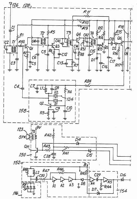
A multi-unit radio control system allows for the simultaneous operation of multiple devices or units using a single remote control transmitter. This system is commonly used in various applications, including model vehicles, drones, and industrial automation.
To design a multi-unit radio control system, several key components and considerations must be addressed:
1. **Transmitter and Receiver Pairing**: The system begins with a transmitter, which sends radio frequency (RF) signals to multiple receivers. Each receiver is paired with a unique identifier to prevent interference and ensure that the correct unit responds to the transmitter's commands. The transmitter can be a handheld device or a more complex control panel, depending on the application.
2. **Frequency Selection**: Selecting an appropriate frequency for communication is crucial. Common frequencies used in radio control systems include 27 MHz, 40 MHz, and 2.4 GHz. The choice of frequency will affect the range and reliability of the system. It is essential to comply with local regulations regarding frequency usage.
3. **Modulation Techniques**: Various modulation techniques can be employed to encode the control signals transmitted from the transmitter to the receivers. Amplitude Modulation (AM), Frequency Modulation (FM), and Digital Pulse Width Modulation (PWM) are commonly used methods. Digital modulation techniques, such as Frequency Hopping Spread Spectrum (FHSS), can enhance the robustness of the communication link.
4. **Power Supply**: Each unit in the multi-unit system will require a power supply. Depending on the design, power can be supplied through batteries, rechargeable cells, or an external power source. Power management is essential to ensure that each unit operates efficiently and has adequate runtime.
5. **Control Logic**: The control logic implemented in each receiver determines how the unit responds to incoming signals. This may involve microcontrollers that interpret the received signals and execute corresponding actions, such as moving motors, activating lights, or controlling other devices.
6. **Range and Antenna Design**: The effective range of the radio control system is influenced by the design of the antennas used in both the transmitter and receivers. Antenna gain, orientation, and placement can significantly affect signal strength and range. Testing different antenna configurations may be necessary to optimize performance.
7. **Interference Management**: In environments where multiple radio control systems operate simultaneously, managing interference becomes critical. Utilizing spread spectrum technology, implementing unique frequency channels, and ensuring proper spacing between units can help mitigate potential conflicts.
8. **Testing and Calibration**: After the initial design and assembly, thorough testing is required to ensure the system functions as intended. Calibration of the transmitter and receivers may be necessary to fine-tune performance, ensuring that each unit responds accurately to commands.
By addressing these components and considerations, a robust and reliable multi-unit radio control system can be developed, suitable for a wide range of applications in both recreational and industrial settings.Multiple unit radio control : How to make a multi-iunit radio control system.. 🔗 External reference
Related Circuits

This design circuit functions to filter out interference signals, ensuring that the signal received from a Morse code station is distinct. The circuit utilizes the earliest mode of radio communications, which employs Morse Code on a continuous wave carrier...
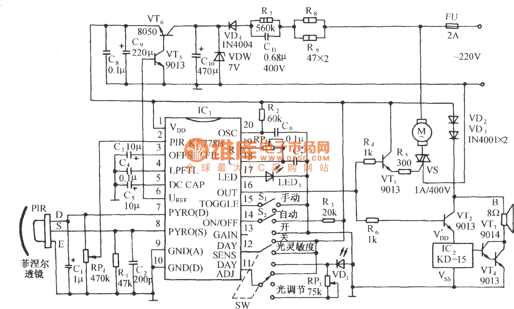
The circuit is depicted in the diagram. It is a control circuit that consists of the infrared-specific integrated circuit KC778B, which serves as the central component. Surrounding it are a pyroelectric infrared sensor head (PIR), a light control and...

The intelligent control circuit for the iron is presented. This circuit utilizes the integrated circuit PT8A351X to manage functions such as direction detection, relay control, and LED indication. When the iron is positioned horizontally, it will power off after...
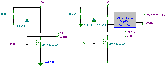
The PWM pulse width modulation controller board enables 9S12/HCS12 microcontrollers or PIC microcontrollers to output 8 channels, each capable of delivering 5 DC amps, while incorporating current sensing for the PWM waveform. This PWM driver circuit is suitable for...
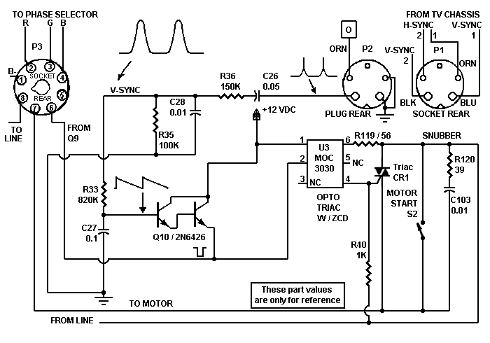
Despite the high impedance of its inputs, the Darlington transistor Q10 generates sufficient current to drive an LED. The inverted output of Q10 powers the internal LED of opto isolator U5, which, in turn, couples to the motor control...

This small device can be aimed at a television to jam the remote control signal. The circuit design is straightforward. A 555 timer is configured as an astable multivibrator operating at a frequency of approximately 38 kHz, which is...