
High Performance Sawtooth Generator

The sawtooth generator circuit operates by utilizing a combination of active and passive components to create a linear ramp voltage that periodically resets. The core of the circuit consists of an operational amplifier configured as a comparator, which is essential for generating the sawtooth waveform. The voltage-controlled current source, formed by the integrated circuit (IC1), resistor (R1), and transistor (Q1), regulates the charge and discharge cycles of the capacitor (C1).
During the discharge phase, when the voltage across C1 drops below 1.66V, the output of the comparator (IC2A) transitions high to 5V, initiating the charging phase. The charging of C1 is facilitated through the diode-connected transistor (Q2), which allows current to flow into C1, raising its voltage until it reaches 3.33V. At this point, the comparator output switches low, effectively resetting the cycle.
The frequency of the output waveform is primarily influenced by the values of C1 and R1. By adjusting these components, the output frequency (fOUT) can be set to a desired level, allowing for a wide range of operational frequencies. However, the maximum achievable frequency is constrained by the slew rate and settling time of the comparator IC2A, which affects how quickly the circuit can respond to changes in voltage.
This sawtooth generator circuit is particularly useful in applications requiring a repetitive waveform, such as in signal processing, modulation, and as a timing reference for other electronic circuits. Its simplicity and low cost make it an attractive solution for various electronic design projects.This is a simple sawtooth generator circuit. The advantages of this circuit are low cost and produces an auxiliary square wave at the same frequency. This circuit can be used to sweep the frequency of another generator. Here is the circuit : A voltage-controlled current source is formed by IC1 with R1 and Q1. The C1 is discharged by current Io unt il it`s voltage is less than 1. 66V. It will swing its output to 5V and trips the IC2A comparator. The C1 is charged by current through the diode-connected transistor (Q2) until its voltage reaches 3. 33V, so the IC2A output to swing back to ground. The output frequency is determined by : We can set the fOUT as high as desired by adjusting the values of C1and R1, subject to the limitations of comparator IC2A`s slew settling and rate time.
The frequency range over which it can operate determined by generator`s linearity. [Source: maxim-ic. com] We aim to transmit more information by carrying articles. Please send us an E-mail to wanghuali@hqew. net within 15 days if we are involved in the problems of article content, copyright or other problems. We will delete it soon. 🔗 External reference
Related Circuits
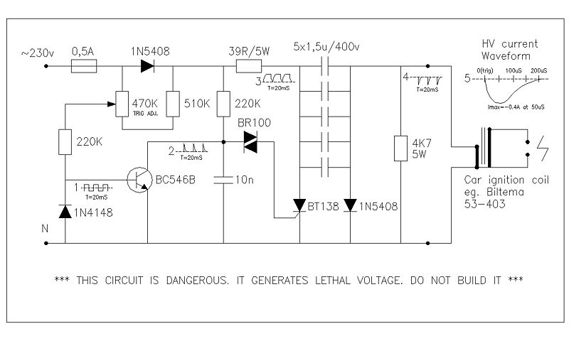
This circuit generates high voltage pulses from a 230 VAC line voltage. The drive end's swing comparator circuit was developed by the creator of this page. The working end is derived from a stroboscope trigger supply circuit. All circuits...
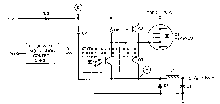
This circuit is essentially a classic buck regulator that utilizes a TMOS N-channel power FET for the chopper and generates its own supply for gate control. The unique feature of this circuit is its method for creating a separate...
This signal generator is designed for the realignment of radio receivers. It is an economical and straightforward unit, adequate for its intended application. However, the output is not a pure sine wave, which may limit its suitability for more...

The preamp being discussed features optional tone and balance controls. While these can be omitted if desired, it is generally not recommended. The input switching capability of this preamp can be extended to accommodate additional signal sources if required. However,...
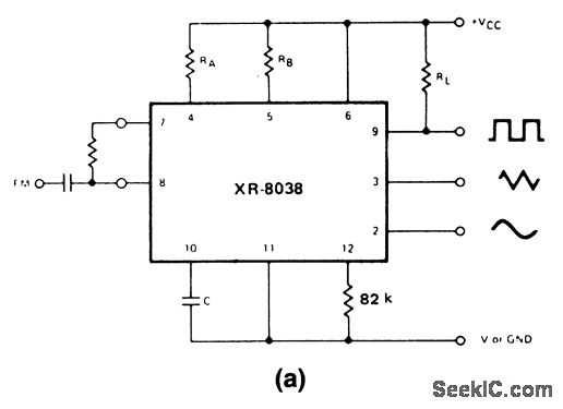
These circuits are similar to that of Fig. 5-47, except that they provide for FM or sweep modulation. Circuit 5-50A is used for FM with small deviations, approximately ±10%. Circuit 5-50B is designed for a sweep range of 1000:1....
This application note describes the implementation of a single-supply triangular wave oscillator using the MAX9000 integrated circuit and several passive components. The circuit employs an operational amplifier, a comparator, and a voltage reference as the main active components. The...