
Marx Generators

The Marx generator operates on the principle of voltage multiplication through a series of stages, each consisting of a capacitor and a switch. In the described 10-stage configuration, the capacitors are charged to a predetermined voltage before the switches are activated. This activation occurs at a specific time in the simulation, which demonstrates the generator's ability to rapidly transition from a charged state to a high-voltage output state. The initial charging voltage (Vo) of 10 kV per stage results in a total output voltage of 100 kV when all capacitors are connected in series.
In practical applications, the choice between resistors and inductors for charging isolation is critical. Resistors, while effective in low-frequency applications, can generate significant heat due to power dissipation at high frequencies, thereby reducing efficiency. Inductors, on the other hand, are preferred in high repetition rate scenarios as they can handle higher power levels with less heat generation, thus maintaining system reliability.
The load resistor in this configuration is crucial for dissipating the energy stored in the capacitors upon discharge. The 100-ohm load resistor is selected to allow for a controlled discharge, providing a clear measurement of the voltage and current waveforms produced by the Marx generator. The voltage across the load resistor (V(RLOAD)) and the current through it (I(RLOAD)) are essential parameters for evaluating the performance of the generator and its suitability for specific applications in pulsed power technology.Marx Generators are often used in pulsed power and high voltage applications to generate a high peak voltage pulse. The simplified theory behind them is that a number of capacitors are charged in parallel and then switches are closed to connect them in series with the charge voltage adding up so that the output voltage is approximately equal to NVo with N being the number
of Marx stages and Vo being the initial charging voltage. In low rep-rate applications, resistors are used as charging isolation components. In high rep-rate applications, the power dissipation within these elements becomes unacceptably large and inductors must be utilized. The circuit schematic for a 10 stage Marx generator is shown below. In this specific model, each stage capacitor is 100nF and is charged to 10 kV. At 1 ms into the simulation, each of the stage switches close and the Marx erects, connecting each capacitor in series.
The equivalent series capacitance (10nF) then discharges into the load resistor with a peak voltage of 100 kV. The results of the circuit model are shown below. V(RLOAD) is the voltage on the 100 ohm load resistor after the Marx fully erects. The circuit current, I(RLOAD) is graphed in the second, lower plot. 🔗 External reference
Related Circuits
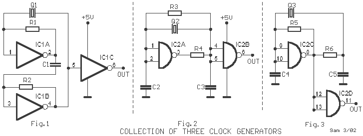
Here exists a small collection from three generators, which use crystals for the basic production of oscillations. Each generator uses a different topology of circuit for the production of oscillations. The described circuit features three distinct oscillators, each utilizing a...
A mechanical power source is required, such as a turbine powered by falling water, a wind turbine, a gas turbine, or a steam turbine. A shaft from one of these devices is connected to a generator to produce power....
The Generator cell must have reasonable surface area on the Plates to generate a reasonable amount of Hydrogen/Oxygen. And a Typical construction would use Stainless Steel for the Electrodes to prevent them from being Quickly eaten away. More: DANGER:...
This circuit generates a two-tone effect similar to the sound of a cuckoo. It can be utilized for doorbells or other applications due to its integrated audio amplifier and loudspeaker. When used as a sound effect generator, it can...
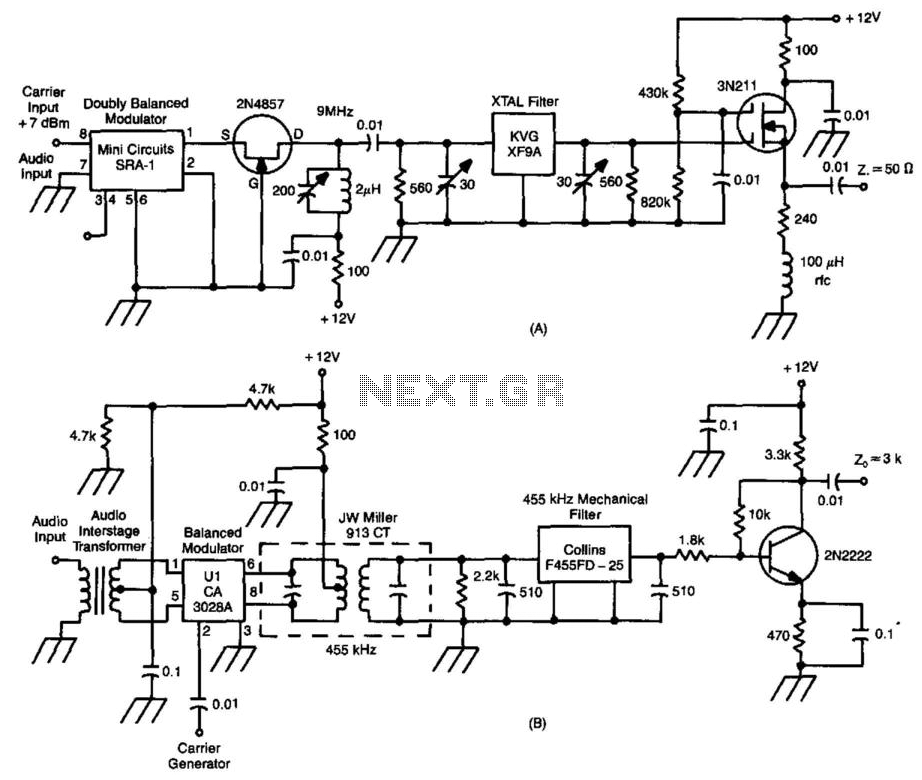
These two circuits are SSB generators. One utilizes a crystal filter by KVG Electronics operating at 9 MHz, while the other employs a 455 kHz mechanical filter. By feeding the outputs into a mixer, the frequency of the SSB...
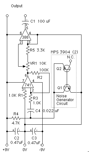
This circuit is effective for testing audio circuits using broadband noise. It employs three inexpensive C-MOS integrated circuits (ICs) that produce a series of output pulses with randomly varying widths. The audio noise generator is designed to drive earphones...