
Hazard lights Coupe 1995
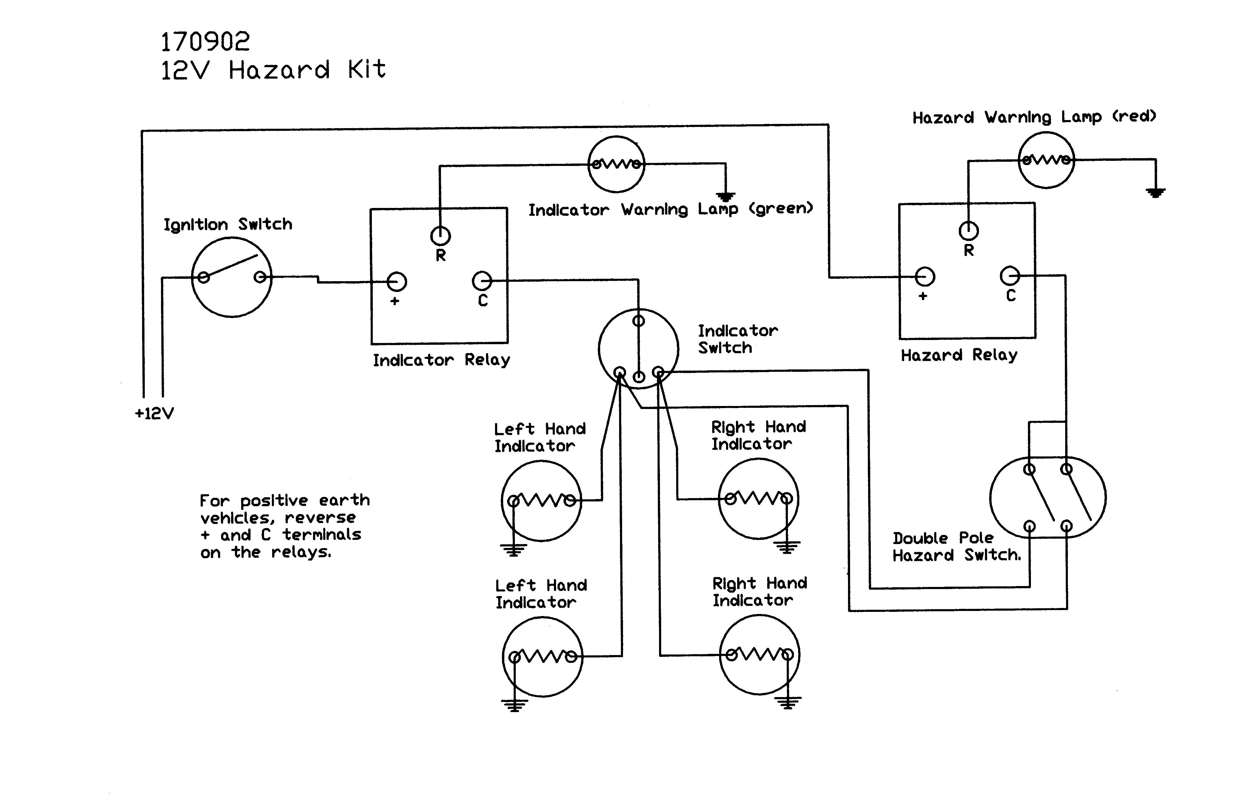
The electronic schematic for the indicator and hazard light system consists of several key components: the indicator switch, hazard switch, relay, and a series of wiring connections. The indicator switch is responsible for controlling the left and right turn signals, while the hazard switch activates all turn signals simultaneously for emergency signaling. The relay serves as an intermediary that controls the power flow to the indicator lights based on the switch positions.
The wiring configuration typically includes four main wires: two for the left and right indicators, one for the common ground, and one for the power supply. However, as noted in the case, a fifth wire may be present, which could lead to complications if it is not accounted for in the system. The presence of this additional wire suggests prior modifications, such as the installation of a tow bar or alarm system, which may have introduced unforeseen issues.
When troubleshooting, it is essential to inspect the wiring harness for any signs of damage, such as frayed insulation or exposed conductors that could be causing a short circuit. The relay should also be tested to ensure it is functioning correctly; a stuck relay can prevent the indicators from operating as intended. Proper grounding is critical in automotive electrical systems, and any disruption in the ground connection can lead to erratic behavior of the lights.
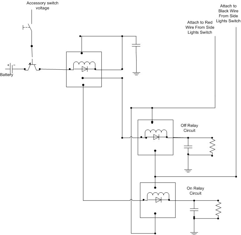
In conclusion, a systematic approach to diagnosing and repairing the indicator and hazard light system is crucial. This involves checking the integrity of the wiring, ensuring the proper functioning of switches and relays, and addressing any modifications that may have been made to the system in the past. Such diligence can help prevent future electrical issues and ensure reliable vehicle operation.This diagram will give you a simplistic idea of how it all works, as you can see the only time left and right come together from the indicator switch is from the stalk to the hazard switch, so get the steering column off too and go all the way from the indicator stalk to the hazard switch it Will be there somewhere dude, it will be! if in step one problem is solved with switch connected source another switch, even if you can find a switch from another vehicle in which wiring is similar might be worth trying that too. Disconnected the haz switch, ran engine. No indicators atall. Changed switch for one I had in the glove box, same fault - hazards or nothing. I`m not electrically minded so I think the car will have to go a specialist to get fixed. just a thought, on that diagram you see the relay for the hazards if that was stuck open it would have same effect, do the hazards work on theyre own i.
e not indicating just hazard button pushed the hazard flasher unit/relay may be the culprit mate, not quite clutching at straws yet i actually think this may have credance. its just the wires that are left after that. all my other research i have done indicates (excuse the pun) a bare wire touching the chassis or another wire in the indicator hazard light circuit.
Have a go at looking at the wires get some panels off search for crimped wires bare wires anything out of place, it is highly likely a short is happening hence its getting better or worse sometimes when its disturbed. Indicators now working. I took the car to a auto elec specialist and within 3hrs had found the problem. He did explain in very basic terms that there are 5 main wires linked to the indicators although there should be 4.
He suspected the 5th was at some point connected to a tow bar or alarm but couldn`t tell which. He cut the 5th wire and hey presto, fault gone so it was obviously broken or shorting somewhere between the dash and it`s end point. So, £42 well spent I`d say ! The way the market is today, around £600, but to be honest with all the new, replaced and repaired parts you`d be better off keeping it unless it really has to go Disclaimer: VW Audi Forum is an "independant
🔗 External reference
Related Circuits
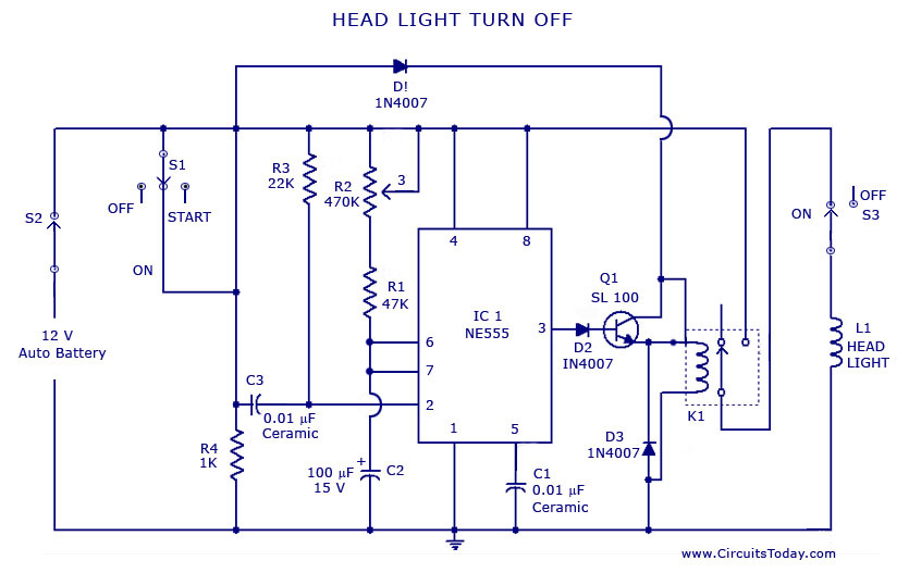
A circuit that can automatically turn off the headlights or lamps of a vehicle after a preset time. This light switching circuit is constructed using a 555 timer integrated circuit (IC). The described circuit utilizes the 555 timer IC in...
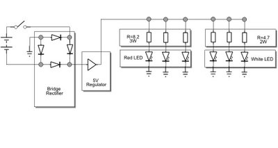
The white LEDs have varying voltage and current requirements, necessitating the use of different resistors. A parts list will be provided. The design concept is similar to previous iterations, but the white LEDs are configured differently due to their...
Automatic color holiday lights circuit The automatic color holiday lights circuit is designed to control the operation of decorative lights during festive seasons. This circuit typically utilizes a microcontroller or a timer to manage the sequencing and color changes...
A decision has been made to install daytime driving lights for an Elise vehicle. The intention is to eliminate the need for manually pressing the button on and off repeatedly. The installation of daytime driving lights (DRLs) enhances vehicle visibility...
This circuit operates at 73 MHz and is designed for controlling halogen lights through radio frequency remote control. The primary function is to toggle the power state of a halogen lamp. When the button on the remote control is...
This simple circuit drives 6 LEDs in Knightrider scanner mode. Power consumption depends mainly on the type of LEDs used if you use a 7555 (555 CMOS version). More: Note that VDD and GND for the ICs are not...