
white lights
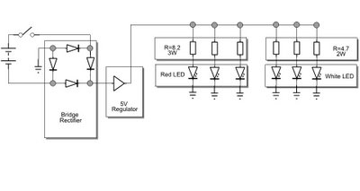
The circuit design involves the integration of multiple white LEDs, each with specific voltage and current ratings, which necessitates careful selection of resistors to ensure optimal performance and prevent damage to the LEDs. The use of heatsinks is crucial for thermal management, as white LEDs tend to generate more heat compared to other colors. The smaller side lamps will be powered by lower-rated LEDs, while the main headlight will utilize higher-rated LEDs to achieve the desired brightness.
The mounting of the rear bullet lights on the trike frame is facilitated by pre-existing holes, which simplifies installation and ensures stability during operation. The wiring connections are made using wire crimps, which provide reliable electrical continuity. The application of black heat-shrink tubing over these connections enhances the durability of the circuit by protecting against moisture and physical damage, while also improving the overall aesthetic.
The choice of 20-gauge lamp wire is suitable for this application, as it balances flexibility and current-carrying capacity. The use of zip ties for wire management ensures that the wiring remains organized and secure, reducing the risk of entanglement or accidental disconnection during operation. The electronics box, housed in a bag behind the seat, is designed to be compact yet functional, providing adequate space for the necessary components while maintaining a low profile.
Overall, this lighting system is designed to provide effective illumination for the trike, with careful consideration given to the electrical specifications and physical layout to ensure both performance and reliability.The white LEDs have different voltage and current requirements so they will need different resistors. So I`ll begin with a parts list: It`s the same idea as before, only the white LEDs are shaped differently because they have their own heatsink that they are mounted on.
The two bullet lights are going to be smaller side lamps, while a large bullet headlight is going to be the main headlight. Here it is opened up. I removed the light bulb but did not bother removing the battery case, as it was riveted in place and would have been very difficult to remove without damaging anything: I mounted the rear bullet lights using some of the premade mounting holes on the trike frame. Also visible are the wire crimps I used to connect up the whole trike. I am going to put black heat-shrink tubing over the crimps so they`re not quite so visible: Finally, all the wires (made of black 20 gauge lamp wire held in place by black zip ties) were run to a bag strapped behind the seat.
The bag is just the right size to hold the electronics box: And there you go! The lights are bright as heck! I calculated the batteries as lasting around 2. 5 hours, but we haven`t tested the system to that limit yet, as we generally recharge the batteries after every ride anyway. 🔗 External reference
Related Circuits
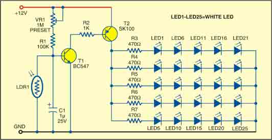
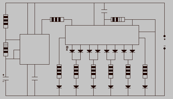
This sunlight-controlled lamp utilizes a light-dependent resistor (LDR) as the sunlight sensor and comprises a total of 25 high-brightness white LEDs. Each row of LEDs is connected in series with separate resistors. The operation of the circuit is straightforward....
Children today appear to possess nearly all the items available in toy stores. Therefore, if there is a son or grandson with a collection of toy cars, here is a suggestion for an addition to that collection. For enhancing a...
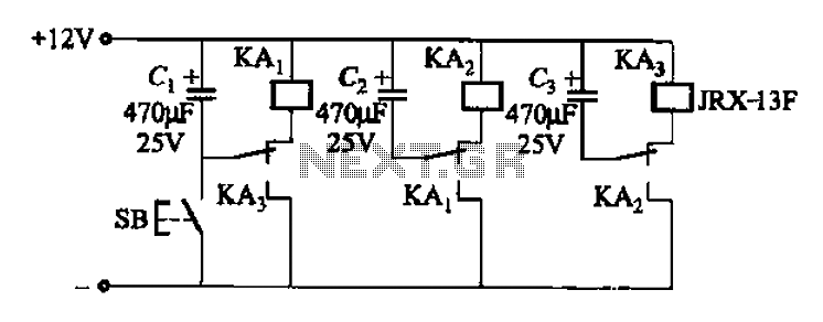
The relay control allows for multiple pairs of contacts to be connected in parallel, enabling the circuit to handle a large lamp power. The design is straightforward; by simply changing the capacitance of the capacitor, different flash frequencies can...
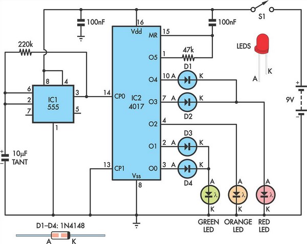
The 555 timer IC is connected for Astable Operation, the clock pulses are fed to the 4017 IC via the 10K resistor. The 4017 is a 10 stage counter, each of the outputs is connected to the appropriate LED,...
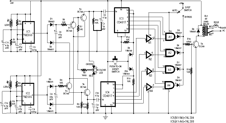
The following circuit illustrates the sensor circuit diagram for automatic room lights. This circuit is based on the CD4017 integrated circuit (IC) and features the use of two light-dependent resistors (LDRs). The automatic room light circuit utilizes the CD4017 decade...
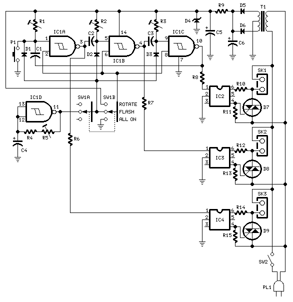
The 15V DC supply is derived from a nominal 230/24V center-tapped AC transformer (T1) and a full-wave rectifier (D5 & D6). A Zener diode (D4) is included to limit the DC voltage to a maximum of 15V. Triacs (D7,...