
head lamp dimmer
The described dimmer circuit is designed to enhance driver safety by effectively managing the brightness of automotive headlamps. The circuit operates by integrating with the existing dimmer switch (S1), allowing for seamless control over the headlamp intensity. When the dimmer switch is engaged, the circuit modifies the voltage supplied to the headlamps, ensuring that the light output does not exceed a safe threshold.
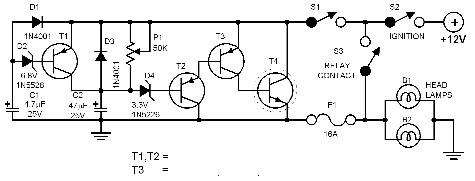
The core component of this dimmer circuit is the potentiometer (P1), which serves as an adjustable resistor. By altering the resistance value, the user can fine-tune the voltage drop across the headlamps, thereby controlling their brightness. This flexibility allows for a personalized adjustment that can accommodate varying driving conditions and individual preferences.
The circuit can be constructed using common electronic components, such as resistors, capacitors, and transistors, which together facilitate the desired dimming effect. A typical configuration may include a transistor that acts as a switch, allowing the circuit to handle the higher current required by the headlamps while maintaining efficient operation.
Additionally, implementing a feedback mechanism could further enhance the performance of the dimmer circuit. By incorporating a light sensor, the circuit could automatically adjust the headlamp brightness based on ambient light conditions, providing optimal visibility without causing glare to oncoming traffic.
In summary, this dimmer circuit offers a practical solution for controlling headlamp brightness in vehicles, contributing to safer driving experiences by preventing excessive light intensity that could impair visibility and pose risks to drivers and pedestrians alike.Every driver knows that a high intensity light striking one`s eyes can have dangerous consequencies. Cars have a dimmer switch to lower the light intensity but unfortunately, some auto headlamps are just too bright even if they are dimmed. The dimmer circuit featured here offers a better solution. When the circuit is activated, it is connected in series to the headlamps through the dimmer switch S1. The brightness of the lamps is then pulled down to a preset level which is determined by the dimmer circuit. The dim level can be preset through the potentiometer P1. 🔗 External reference
Related Circuits
Savings on electricity bills can be achieved by utilizing alternative power sources. The photovoltaic module, or solar panel, described here can provide a power output of 5 watts. Under full sunlight conditions, the solar panel generates an output voltage...
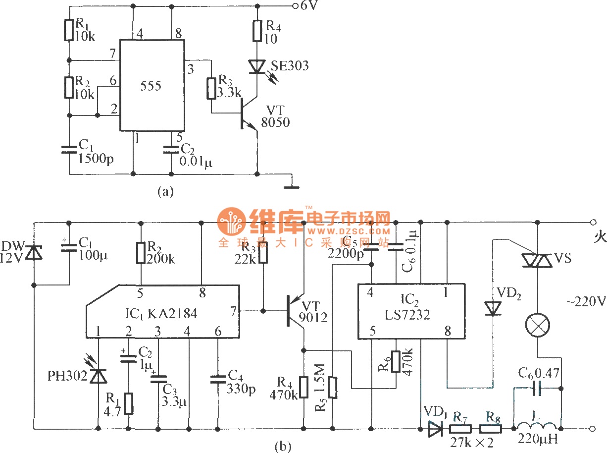
This is an infrared emission circuit diagram. The NE555 circuit generates a 40 kHz pulse, which is sent by the infrared emission control SE303 after being amplified by VT. The remote receiver and infrared dimming circuit are composed of...

The following circuit illustrates a Bedside Lamp Timer Circuit Diagram. This circuit is based on the CD4060 integrated circuit. Features: An LED illuminates for approximately 25 seconds. The Bedside Lamp Timer Circuit utilizes the CD4060 IC, which is a versatile...
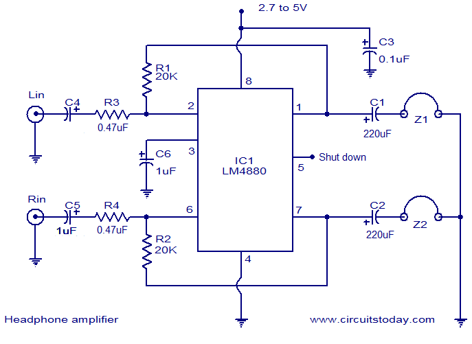
The LM4880 is a high-fidelity dual audio amplifier integrated circuit (IC) from National Semiconductors. This IC is specifically designed to deliver high-quality audio output with a minimal number of external components. The LM4880 can provide 250mW per channel into...
The electronic lantern control circuit adds high-efficiency dimming and flashing to an existing battery-powered lantern or flashlight or to a custom design. For the car it makes a great lamp for changing a flat tire, back seat reading or...
Both halves of the circuit are identical. Both inputs have a DC path to ground via a 47k control, which should be a dual logarithmic type potentiometer. The balance control is a single 47k linear potentiometer, which, when adjusted...