
IR remote control dimmer light circuit diagram
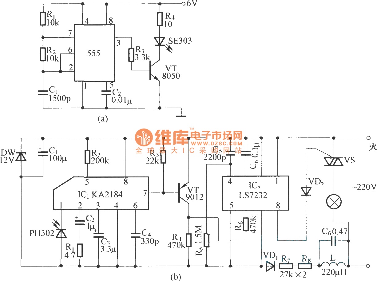
The infrared emission circuit utilizes the NE555 timer IC configured in astable mode to produce a continuous square wave output at a frequency of 40 kHz. This frequency is optimal for infrared communication, allowing the emitted pulses to be modulated for efficient transmission. The NE555 output drives the SE303 infrared emitter, which converts the electrical pulses into infrared light.
The SE303 acts as an infrared LED driver, amplifying the pulse signal from the NE555. The transistor VT is employed to further amplify the current, ensuring that the infrared LED emits sufficient intensity for effective communication over a distance. The choice of VT is critical, as it must be capable of handling the required current without overheating or entering saturation.
On the receiving end, the KA2184 serves as the infrared receiver and dimming controller. It detects the modulated infrared signal and demodulates it to retrieve the original pulse signal. This IC is designed to operate efficiently in low-light conditions, making it suitable for applications such as remote controls and dimming systems.
The LS7232 integrated circuit is utilized in conjunction with the KA2184 for advanced dimming capabilities. It provides additional features such as adjustable brightness levels, allowing users to control the intensity of the output light based on the received infrared signals. The integration of these components results in a robust system capable of precise control over infrared lighting applications, enhancing both functionality and user experience.
Overall, this circuit represents a comprehensive solution for infrared emission and reception, integrating multiple components to achieve effective communication and control in electronic lighting systems.Is infrared emission circuit diagram. NE555 circuit generates a 40kHz pulse which is sent by the infrared emission control SE303 after beingamplified by VT. (b) is remote receiver and infrared dimming circuit composed of the KA2184. LS7232 is an integrated dimming circuit. 🔗 External reference
Related Circuits
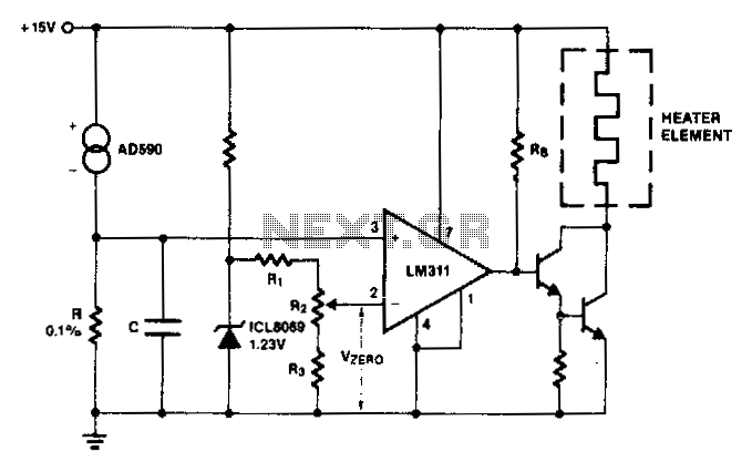
The AD590 generates a voltage that varies with temperature across resistor R, while capacitor C serves to filter out noise. To establish a zero-scale voltage, resistor R2 is adjusted. For the Celsius temperature scale, R should be set to...
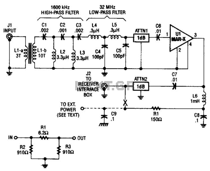
The HF/SW receiver preamplifier consists of a broadband toroidal transformer (LI-a and Ll-b), an LC network featuring a 1600-kHz high-pass filter and a 32-MHz low-pass filter, inductors L2 and L3 (26 turns of #26 enameled wire wound on an...
The WPG DM8168 DaVinci high-definition video System on Chip (SoC) offers multiple DVR/NVR surveillance solutions, utilizing the MT9M033 image sensor as a key component in safety monitoring systems. This solution is complemented by Conexant's line of multi-channel video surveillance...
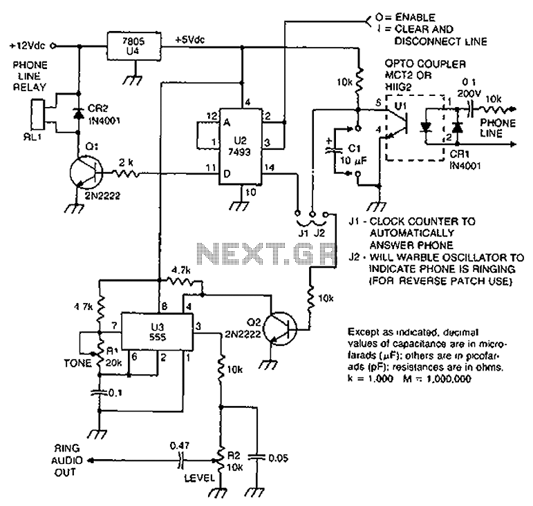
Check the loop circuit for an automatic telephone answering system or a tone generator for use in reverse automatic repair. The loop circuit in an automatic telephone answering system is designed to detect incoming calls and activate the answering mechanism....
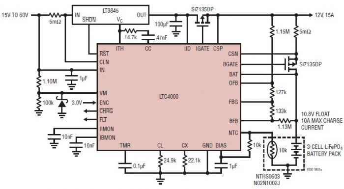
The LTC4000 high voltage controller, developed by Linear Technology, can be utilized to create a straightforward high current LiFePO4 battery charger. This charger delivers a fixed output voltage of 12 volts with a maximum output current of 15 A....
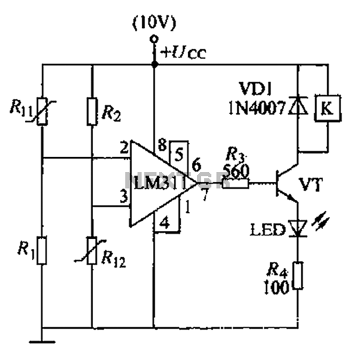
A boiler control circuit is designed to regulate the temperature of water in a hot water heating system. This circuit typically utilizes a comparator's comparison function to manage the heating equipment. The circuit includes a thermistor that forms a...
Warning: include(partials/cookie-banner.php): Failed to open stream: Permission denied in /var/www/html/nextgr/view-circuit.php on line 713
Warning: include(): Failed opening 'partials/cookie-banner.php' for inclusion (include_path='.:/usr/share/php') in /var/www/html/nextgr/view-circuit.php on line 713