
Head light timer circuit

The compact timer circuit described operates as a headlight delay mechanism, enhancing convenience and safety for vehicle users. The core components include a push button switch (P1), a capacitor (C1), resistors (R1), and transistors (Q1 and Q2), along with a relay (K1) that controls the headlights.
Upon pressing switch P1, capacitor C1 begins to charge, reaching the battery voltage level. Transistor Q1 serves as a switch that allows current to flow from the charged capacitor to transistor Q2. When Q2 is activated, it energizes relay K1, which closes its contacts and powers the headlights. The relay is critical as it provides the necessary current to operate the headlights without overloading the transistors.
The timing aspect of the circuit is primarily influenced by the RC time constant, which is determined by the values of the capacitor (C1) and the resistor (R1). The product of these values dictates how long it takes for the capacitor to discharge sufficiently to turn off the transistors, thereby deactivating the relay and extinguishing the headlights. In this specific design, the components have been selected to achieve a delay of 1.5 minutes, providing ample time for users to exit the vehicle and navigate safely in low-light conditions.
Overall, this timer circuit is a practical solution for maintaining headlight illumination after the vehicle has been turned off, ensuring that drivers can safely navigate their surroundings without the risk of draining the car battery or forgetting to switch off the lights. Proper implementation of this circuit can enhance the functionality and user experience of automotive lighting systems.This circuit is a compact timer circuit that will keep the headlights of your car ON for about 1. 5 minutes and then turns it OFF. This circuit incorporated to your car will help you to access dark places with out the need to come back and turn OFF the head lights. When the push button switch P1 is pressed the capacitor C1 is charged to the full bat tery voltage. As a result the transistor Q1 is turned ON, which in turns ON Q2 which in turns drives the relay K1 to glow the head lights. The relay K1 will remain activated until the capacitor C1 is fully discharged. The time delay of the circuit depends on values of C1 & R1 and here it is set to be 1. 5 minutes. 🔗 External reference
Related Circuits
PWM waveforms are widely utilized to regulate the speed of DC motors. The duty cycle of the digital waveform can be established either through an adjustable analog voltage level (as seen in a NE555-based PWM generator) or through digital...
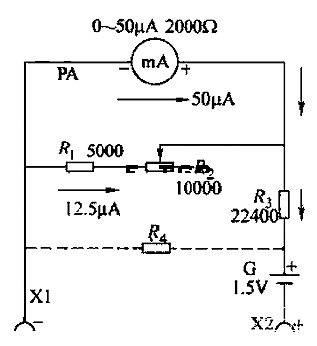
A commonly used high-sensitivity header utilizes a microammeter to create a resistance meter capable of measuring very low voltages. The design adheres to the principles of a milliameter resistance meter. The circuit diagram is illustrated in Figure 5-37, which...
Most recent cars are equipped with a significant amount of electronics, including ABS brake systems, engine control with injection calculators, airbag activation, and various comfort functions. One such function, often overlooked due to its commonality, is the automatic activation...

Below 10 MHz, the development of engineering models is relatively straightforward and not significantly influenced by printed circuit board layout. In the VHF range, parasitic circuit elements and unwanted coupling can severely impact efforts to achieve cost-effective performance without...
This is a pressure sensor signal conditioning circuit. It is a simple and inexpensive circuit due to its small geometry and the use of a straightforward pressure sensor. The pressure sensor signal conditioning circuit is designed to convert the raw...
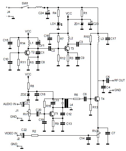
The circuit converts audio and video signals into a UHF TV signal, allowing a video signal from a camera or other source to be connected to a standard TV set. The audio and video signals are transformed into a...