
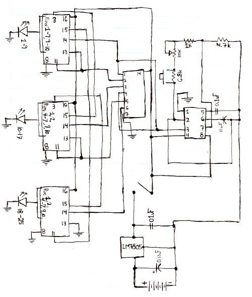
LED Knight RiderCircuit With 4017 and 555 IC
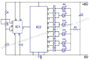
The LED Knight Rider circuit is designed to create a visual effect reminiscent of the iconic "Knight Rider" television series, where lights move back and forth in a sequential pattern. The core components of this circuit are the 555 timer IC, which operates in astable mode to generate a continuous pulse, and the 4017 decade counter IC, which is used to drive the LEDs in a sequence.
In this circuit, the 555 timer is configured to produce a clock signal that toggles at a predetermined frequency. This frequency can be adjusted by varying the resistor and capacitor values connected to the 555 timer. The output of the 555 timer is fed into the clock input of the 4017 IC, which counts the pulses and activates the corresponding outputs in a sequential manner.
The 4017 IC has ten output pins, but in this specific design, only four outputs are utilized to control four LEDs. As the 4017 counts the pulses from the 555 timer, it sequentially turns on each LED one after the other, creating the desired running light effect. When the last LED is turned on, the 4017 resets, and the cycle begins again, resulting in a continuous back-and-forth movement of the lights.
The circuit requires a power supply, typically in the range of 5V to 15V, depending on the specifications of the components used. The LEDs can be connected in series with current-limiting resistors to prevent excessive current flow, ensuring their longevity. Overall, this circuit is an excellent demonstration of basic digital electronics principles and provides a visually appealing effect for various applications.The following circuit shows about LED Knight Rider Circuit Diagram. This circuit based on the 4017 and 555 IC. Features: Knight Rider circuit, 4 .. 🔗 External reference
Related Circuits
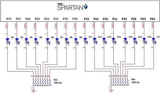
The Spartan-6 board features 16 LEDs connected to FPGA I/O pins, as detailed in the table below. The cathode of each LED is connected to ground through a 330-ohm resistor. To illuminate a specific LED, the corresponding FPGA control...

This simple circuit drives six LEDs in a "Knightrider scanner mode." Power consumption primarily depends on the type of LEDs used, particularly when utilizing a 7555 (the CMOS version of the 555 timer). The circuit is designed to create a...
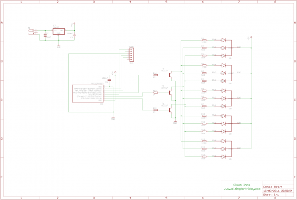
This project involves creating an RGB LED-lit love heart controlled by a PIC12F683 microcontroller. The design serves as a gift for a 15th wedding anniversary. The heart is crafted from a 200x150x6mm sheet of plexiglass, which is cut and...

This project describes a light effect that is similar to the one of the car in the TV series "Knight Rider." The light effect project emulates the iconic scanning LED light sequence featured in the "Knight Rider" television series. The...
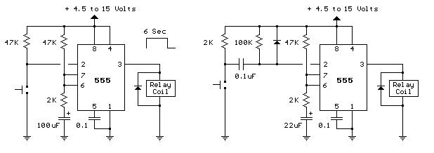
The two circuits demonstrate the use of a 555 timer to activate a relay for a specified duration when a momentary normally open (N/O) push button is pressed. The circuit on the left is designed for extended time periods,...
Here is the schematic for the circuit. Solder all the components onto a perfboard. The drawings may not be very clear. Essentially, the 555 timer generates a pulse. The circuit utilizes a 555 timer IC configured in astable mode, which...
Warning: include(partials/cookie-banner.php): Failed to open stream: Permission denied in /var/www/html/nextgr/view-circuit.php on line 713
Warning: include(): Failed opening 'partials/cookie-banner.php' for inclusion (include_path='.:/usr/share/php') in /var/www/html/nextgr/view-circuit.php on line 713