
Headlight Flasher
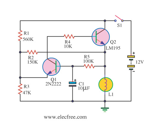
The circuit operates by employing the NE555 timer in astable mode, which allows it to generate a continuous square wave output. This output is connected to a relay that controls the headlights, enabling them to turn on and off at a specified frequency. The frequency of the flashing can be adjusted by changing the resistor and capacitor values connected to the timer.
In a typical setup, the circuit includes the NE555 timer IC, a few passive components such as resistors and capacitors, and a relay capable of handling the current drawn by the headlights. The NE555 timer is powered by the vehicle's battery, ensuring that it operates effectively even when the vehicle is stationary.
The use of the relay is crucial as it isolates the low-power timer circuit from the high-power headlights, preventing any potential damage to the timer IC. The circuit can be further enhanced with additional features such as a variable resistor to adjust the flashing rate, or diodes to protect against back EMF generated by the relay.
Overall, this circuit serves as an engaging project for automotive enthusiasts, providing a practical application of the NE555 timer while enhancing vehicle visibility through the flashing headlights.Small and interesting circuit that flashes your head lights. Automotive, head lights, circuit diagram. Built around famous NE555 timer circuit.. 🔗 External reference
Related Circuits
If you require a small lamp that flashes for general use, there are numerous options available. Today, three lamp flasher circuits will be presented. The three lamp flasher circuits can be designed using different components and configurations, each offering unique...
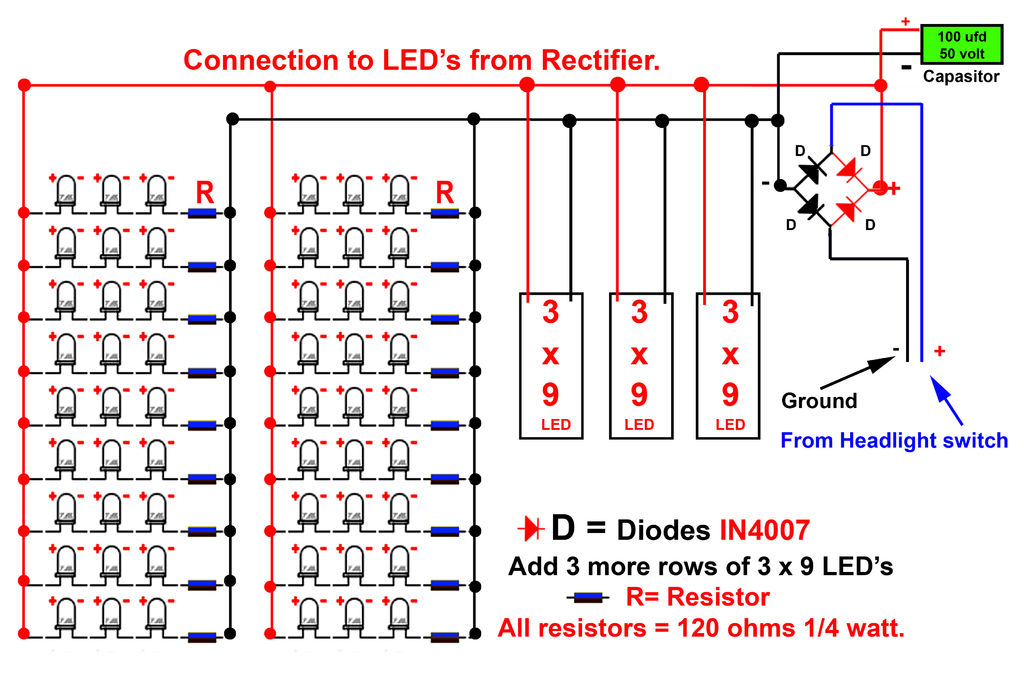
Gently bend the leads of the LEDs and, using the provided schematic circuit diagram, begin to solder. Once soldering is complete, it should... To successfully assemble the LED circuit, it is essential to follow a systematic approach. Start by preparing...
This circuit functions as a phone message flasher, providing an alternative method to alert users of an incoming call. When the phone rings, a high line voltage is activated. The phone message flasher circuit is designed to enhance the traditional...
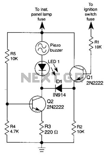
The base of Q1 is connected to the car's ignition circuit; the easiest point to make that connection is at the ignition switch fuse in the car's fuse panel. Also, one side of the piezoelectric buzzer is connected to...
This is a simple 1.5V powered LED flasher circuit diagram. This circuit can flash 1.7V or 2.3V LEDs (depending on the color) using a 1.5V DC input. The LED will turn on when the 100µF capacitor is charged by...
Motor Bike Headlight Controller Circuit. This circuit automatically turns a motorcycle's headlight on and off, independently of both the light and ignition switches, provided the battery is fully charged. The first stage... The motorcycle headlight controller circuit is designed to...