
Headlight Flasher with 555
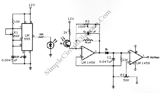
The described circuit utilizes a 555 timer integrated circuit configured in astable mode to achieve a flashing headlight effect for automotive applications. In this configuration, the 555 timer oscillates between high and low output states, generating a square wave signal that controls the operation of relays responsible for the headlight flashing.
The frequency of the flashing can be adjusted by varying the resistance of R1, which influences the charge and discharge times of the timing capacitor connected to the 555 timer. This flexibility allows for customization of the flash duration according to user preferences.
To integrate this circuit into a vehicle's headlight system, it is essential to identify the positive lead from the fuse box that supplies power to the headlights. This wire must be cut, and a relay contact should be inserted in series to control the power flow to the headlights based on the output from the 555 timer. The inclusion of a bypass switch in the circuit enables the user to revert to standard headlight operation without the flashing feature, providing convenience and safety.
For the alternating headlight flashing configuration, each headlight's positive wire must be severed, and additional relay contacts must be connected to control each headlight independently. This setup allows for a dynamic flashing effect, enhancing visibility and signaling capabilities while driving.
Overall, this circuit design offers a practical solution for automotive lighting customization, leveraging the capabilities of the 555 timer and relay systems to achieve desired headlight functionalities. Proper implementation requires careful attention to wiring and safety protocols to ensure reliable operation within the vehicle's electrical system.is circuit was requested from an email. It will allow your car headlights to flash on and off at the same time or it will cause them to flash alternately. The circuit is based on the 555 timer. It is used in the astable mode. The 555 timer output will go high for an adjustable period of time and then turn off. It will then repeat the procedure. The time is adjusted by R1. To hook up the circuit to your car you must locate the positive wire from the fuse box to the headlights.
Cut the wire and insert the relay contact and bypass switch. The bypass switch will allow you to bypass the relay contact for normal headlight operation. In the alternating headlight configuration you must cut the positive wire to each headlight and wire in the relay contact. 🔗 External reference
Related Circuits
This circuit provides a visual 9 second delay using a 7 segment digital readout LED. When the switch is closed, the CD4010 up/down counter is preset to 9 and the 555 timer is disabled with the output held high....
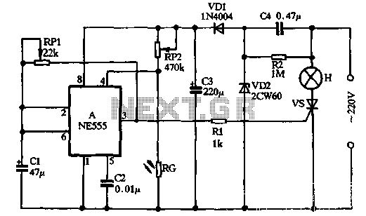
VDI, VD2, C3, and C4 form a simple half-wave rectifier capacitor step-down regulator circuit. This circuit can output approximately 12V DC voltage after power is applied across C3, which is utilized for the time base circuit. Additionally, the time...
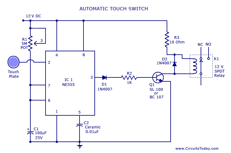
A touch switch circuit schematic utilizing a 555 integrated circuit (IC). When the touch plate is activated, a relay is switched ON for a predetermined duration, which can also be adjusted. The touch switch circuit employs a 555 timer IC...
The output of the transformer has been calculated to be 125 times higher than the input, based on the ratio of 1000 to 8. Given an input of 12V, the expected output should be 1500V, although there is some...
The infrared transmitter and receiver circuit depicted in the schematic diagram below can function as a remote control. The transmitter primarily operates as an oscillator. The infrared transmitter and receiver circuit is designed to facilitate wireless communication through infrared signals,...

There have described the involvement benefited LM3909 circuit, which is quite expensive. That's why I prefer to use a much cheaper known timer 555th. Involvement of the tree is a very simple scheme is to figure 2. It is...